3-4
Theory of Operation:
Main Board
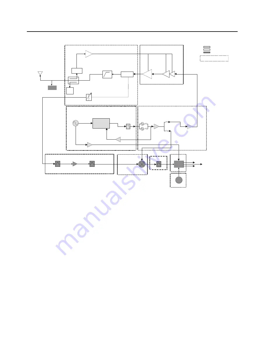
Figure 3-3. Transceiver (VHF) Block Diagram (Power and Control Omitted)
FGU
Transmitter
Receiver
2nd
LO
Digital
RF Atten
Antenna Switch
coupler
Rev
Power
Detector
Log
Amp
FET
TRIDENT IC
LOOP
FILTER
PRESCALAR
BUFFER
RX SSI Data
16.8MHz
BUFFER
PRE
BUFFER
TX LO
TX
BUFFER
TX
RX
*
16.8MHz
RX SSI Clock
RX SSI Frame Sync
Indicates Sub-shield
Harmonic
Filter
Driver
Amplifier
*
Abacus
IF Filter
15dB Step Attn
RX VCO
TX VCO
VHF
LNA
VHF
Mixer
GPS
Summary of Contents for Astro APX 3000
Page 1: ...APXTM TWO WAY RADIOS APX 3000 DETAILED SERVICE MANUAL ...
Page 2: ......
Page 4: ...Notes ...
Page 6: ...vi Document History Notes ...
Page 10: ...x Table of Contents Notes ...
Page 12: ...xii List of Tables Notes ...
Page 18: ...xviii List of Figures Notes ...
Page 22: ...xxii CommercialWarranty Notes ...
Page 46: ...3 20 Theory of Operation Main Board Notes ...
Page 84: ...3 58 Theory of Operation Bluetooth Notes ...
Page 208: ...6 64 Troubleshooting Waveforms LF CW on Spectrum Analyzer Notes ...
Page 222: ...7 14 Troubleshooting Tables List of Board and IC Signals Notes ...
Page 282: ...8 60 Schematics Boards Overlays and Parts Lists Main Board Block UHF1 84012513001_A Notes ...
Page 390: ...8 168 Schematics Boards Overlays and Parts Lists Main Board Block VHF 84012512001_A Notes ...
Page 456: ...9 8 Debugging Fixture Powering up Covert Board Notes ...
Page 468: ...Glossary 10 Glossary Notes ...
Page 472: ...Index 4 Index Notes ...
Page 473: ......


