5-50
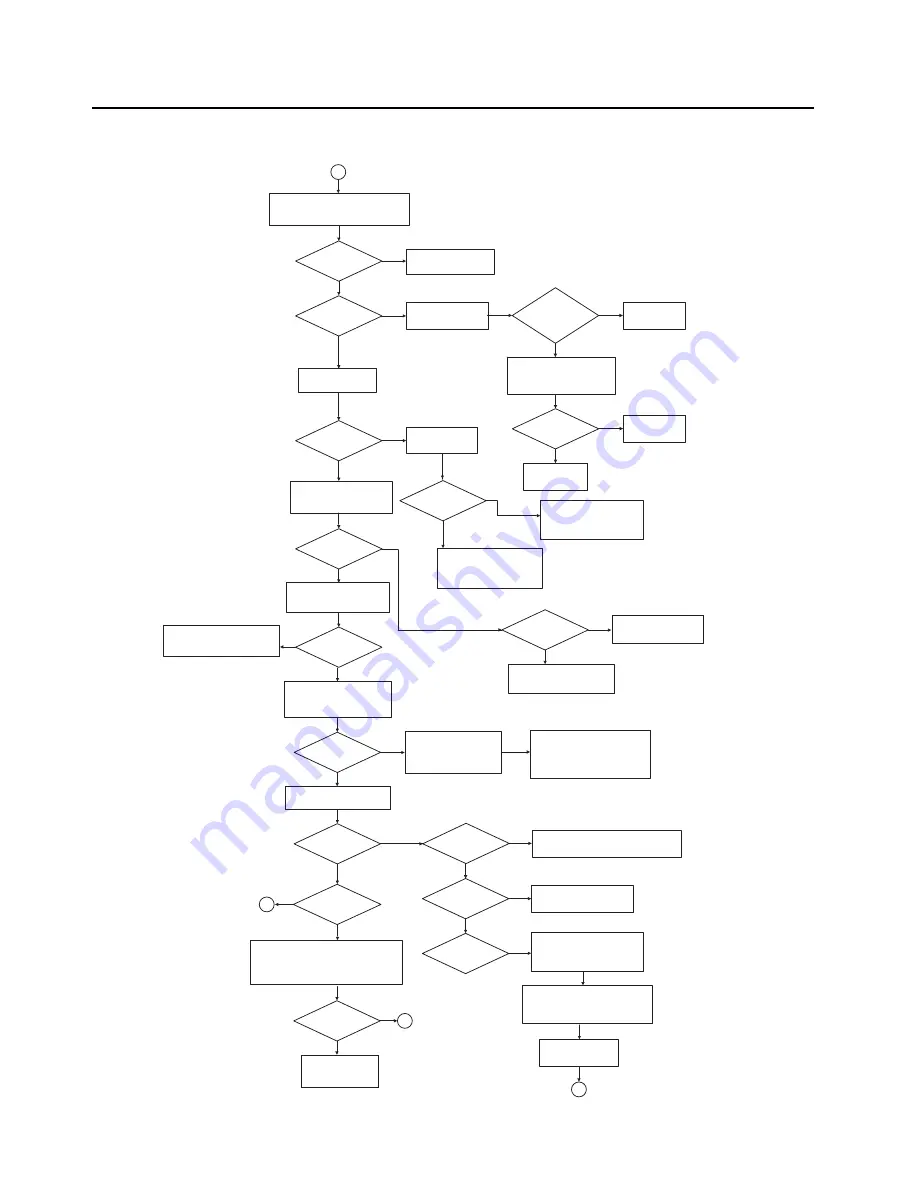
Troubleshooting Charts:
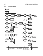
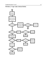
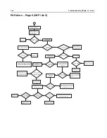
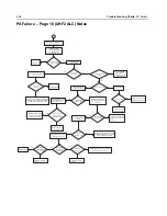
PA Failure
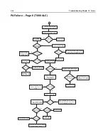
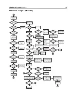
PA Failure – Page 2 (VHF PA)
No
Yes
No
No
Yes
Yes
No
Yes
No
No
Yes
Yes
No
No
Yes
Yes
No
No
Yes
Yes
Yes
Yes
No
Yes
No
Yes
Yes
No
Yes
No
2
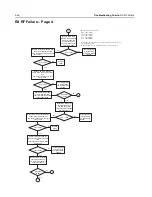
Remove shield SH5. On a spectrum
analyzer measure input frequency
and power level at C901.
Is frequency and
spectrum of the
signal OK?
Is power level
above 0 dBm?
Was voltage
near 7.5 V?
See FGU
troubleshooting charts.
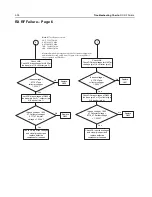
Measure power level
at pin 5 of U1110.
Was the change
in power level
more than 2 dB
higher?
Check voltage on pins 4 and
6 of U1110, pin 4 should be
near 0 V and pin 6 should
be near 2.775V.
See FGU
troubleshooting
charts.
Were the
voltages
correct?
See FGU
troubleshooting
charts.
Replace U1110.
Measure DC voltage
on C903 and C905.
Measure voltage
at pin 1 of Q1101.
Was voltage
near 3 V?
Trace voltages and check
for solderability issues on
R1102, Q1101, and Q1103.
Replace parts as necessary.
Measure inputs on pins 2
and 3 to AND gate U1119.
Pin 2 and 3 should be 5
and 2.775V respectively.
With the radio in RX mode,
measure the DC voltage
on both pins of L903.
Was voltage
near 7.5 V on
both sides?
Check L903 for solderability
issues and replace as
necessary.
With the radio in RX mode,
measure the DC voltage
on the drain of Q901.
Was voltage
near 7.5 V?
Check L906 under sheild SH10
for solderability issues and
replace as necessary.
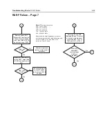
Is there 7.5 V on
C908?
Check E1101 for
solderability issues and
replace as necessary.
With the radio in RX mode,
measure the resistance on
the node shared by C916
and R906.
the resistance
Is
near 9.4k
Ohms?
Check resistors R901,
R902, R903, R904, and
R905 for resistance and
solderability issues and
replace as necessary.
If resistance is very low, in the
100's of ohms,and there are no
issues with the resistors then
there is a gate short on the PA.
Clear short or replace Q901.
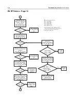
In TX mode, measure the
voltage on pin 4 of U901.
Is the voltage
near 6 V?
the TX current
Is
between 300 and
900 mA?
The PA is likely damaged.
Replace Q901.
the TX current
Is
above 900 mA?
Lift shield SH10 and check
for solderability or part issues
on all 900 series parts.
Replace parts as necessary.
If no issues found, lift shield SH13
and check for solderability or part
issues on all 1200 series parts.
Replace parts as necessary.
4
TX current
Is
just above
stanby current?
If power issue is not
resolved.
The PA and Driver are likely damaged.
Replace Q901 and U902.
Is the voltage
below 4 V?
5
If the voltage is between 4 and 5.5V
working and power should be
then the control loop should be
available. Check the coaxial cables
and surface mounted coaxial connectors.
Were the
connections
OK?
3
Replace cables, or
connectors J101 or
J102.
Summary of Contents for ASTRO APX 7000
Page 1: ......
Page 4: ...iv Document History Notes ...
Page 24: ...2 4 Radio Power DC Power Routing VOCON Board Notes ...
Page 98: ...3 74 Theory of Operation Global Positioning System GPS ...
Page 163: ...Troubleshooting Charts PA Failure 5 59 ...
Page 164: ...5 60 Troubleshooting Charts PA Failure ...
Page 276: ...7 58 Troubleshooting Tables List of Board and IC Signals Notes ...
Page 318: ...8 42 Schematics Boards Overlays and Parts Lists Transceiver RF Boards VHF 700 800 Notes ...
Page 380: ...8 104 Schematics Boards Overlays and Parts Lists Transceiver RF Boards UHF1 700 800 MHz Notes ...
Page 432: ...8 156 Schematics Boards Overlays and Parts Lists Transceiver RF Boards UHF1 VHF Notes ...
Page 458: ...8 182 Schematics Boards Overlays and Parts Lists Transceiver RF Boards UHF1 UHF2 Notes ...
Page 498: ...8 222 Schematics Boards Overlays and Parts Lists Transceiver RF Boards UHF2 700 800 MHz Notes ...
Page 546: ...8 270 Schematics Boards Overlays and Parts Lists Transceiver RF Boards UHF2 VHF Notes ...
Page 606: ...8 330 Schematics Boards Overlays and Parts Lists VOCON Boards Notes ...
Page 638: ...Glossary 10 Glossary Notes ...
Page 643: ......

