Chapter 3 Theory of Operation
This chapter provides a detailed circuit description of the ASTRO APX 7000/ 7000XE transceiver
and VOCON boards. When reading the theory of operation, refer to the appropriate schematic and
component location diagrams located in the back of this manual. This detailed theory of operation
can help isolate the problem to a particular component.
The ASTRO APX 7000/ 7000XE radio, which is a wideband, synthesized radio available in the
VHF (136–174 MHz), UHF1 (380–470 MHz), UHF2 (450–520 MHz), or 7/800 (764–870 MHz)
frequency bands, as well as dual-band combinations of VHF/7/800, UHF1/VHF, UHF1/7/800,
UHF2/VHF, UHF2/7/800, and UHF1/UHF2. All ASTRO APX 7000/ 7000XE radios are capable of
both analog operation (12.5 kHz or 25 kHz bandwidths), ASTRO mode (digital) operation
(12.5 kHz only) and X2-TDMA mode (25 kHz only).
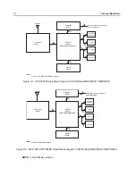
The ASTRO APX 7000/ 7000XE radio (
Figure 3-1
) consists of the following:
•
VOCON Board
– contains a dual-core processor which includes both the microcontroller unit
(MCU) and a digital signal processor (DSP) core, the processor's memory devices, an audio
and power supply support integrated circuit (IC), a digital support IC, external audio power
amplifier, and Type III secure IC.
•
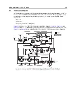
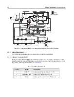
Transceiver (XCVR) Board
– contains all transmit, receive, and frequency generation circuitry,
including the digital receiver back-end IC and the reference oscillator.
•
Expander Board
– contains the internal audio power amplifier circuitry and the Global
Positioning System (GPS) IC and support circuitry.
•
Bluetooth Option Board
– contains a microprocessor and memory, Bluetooth circuitry, MPP
(Motorola Proximity Pairing) circuitry, and an accelerometer.
•
Top Display
– 112 pixels x 32 pixels, transflective monochrome liquid crystal display (LCD).
(APX 7000 utilizes a 1.1" diagonal display while APX 7000XE utilizes a 1.2" diagonal display)
•
Control Top
– contains five switches: On/Off & Volume Knob, a 16 position Channel/Frequency
Knob with concentric 2 position switch (for Secure Enable/Disable operation), a 3 position
toggle switch for Zone Selection, and a push button switch used for Emergency calling. The
control top also includes an TX/RX LED that is solid amber upon receive, red on PTT, and
blinks amber on secure TX/RX.
•
Front Display (Dual-Display Version only)
– 320 pixels x 240 pixels, transflective color LCD.
•
Keypad (Dual-Display Version only)
– Dual-Display version has a 3 x 2 Menu keypad with
4-way navigation button, and a 3 x 4 alphanumeric keypad.
Summary of Contents for ASTRO APX 7000
Page 1: ......
Page 4: ...iv Document History Notes ...
Page 24: ...2 4 Radio Power DC Power Routing VOCON Board Notes ...
Page 98: ...3 74 Theory of Operation Global Positioning System GPS ...
Page 163: ...Troubleshooting Charts PA Failure 5 59 ...
Page 164: ...5 60 Troubleshooting Charts PA Failure ...
Page 276: ...7 58 Troubleshooting Tables List of Board and IC Signals Notes ...
Page 318: ...8 42 Schematics Boards Overlays and Parts Lists Transceiver RF Boards VHF 700 800 Notes ...
Page 380: ...8 104 Schematics Boards Overlays and Parts Lists Transceiver RF Boards UHF1 700 800 MHz Notes ...
Page 432: ...8 156 Schematics Boards Overlays and Parts Lists Transceiver RF Boards UHF1 VHF Notes ...
Page 458: ...8 182 Schematics Boards Overlays and Parts Lists Transceiver RF Boards UHF1 UHF2 Notes ...
Page 498: ...8 222 Schematics Boards Overlays and Parts Lists Transceiver RF Boards UHF2 700 800 MHz Notes ...
Page 546: ...8 270 Schematics Boards Overlays and Parts Lists Transceiver RF Boards UHF2 VHF Notes ...
Page 606: ...8 330 Schematics Boards Overlays and Parts Lists VOCON Boards Notes ...
Page 638: ...Glossary 10 Glossary Notes ...
Page 643: ......

