Chapter 3
Theory of Operation
This chapter provides a detailed circuit description of the ASTRO XTS 5000 transceiver and VOCON
boards. When reading the theory of operation, refer to the appropriate schematic and component
location diagrams located in the back of this manual. This detailed theory of operation can help
isolate the problem to a particular component.
The ASTRO XTS 5000 radio is a dual-mode (digital/analog), microcontroller-based transceiver
incorporating a digital signal processor (DSP). The microcontroller handles the general radio control,
monitors status, and processes commands input from the keypad or other user controls. The DSP
processes the typical analog signals, and generates the standard signaling digitally to provide
compatibility with existing analog systems. In addition, the DSP provides digital modulation
techniques, utilizing voice encoding techniques with error correction schemes. This provides the
user with enhanced range and audio quality, all in a reduced bandwidth channel requirement. It
allows embedded signaling, which can mix system information and data with digital voice to support
a multitude of system features.
The three ASTRO XTS 5000 radio models (I, II, and III) are available in the VHF (136 to 174 MHz),
UHF Range 1 (380 to 470 MHz), UHF Range 2 (450 to 520 MHz), and 700–800 MHz (764 to
870 MHz) frequency bands.
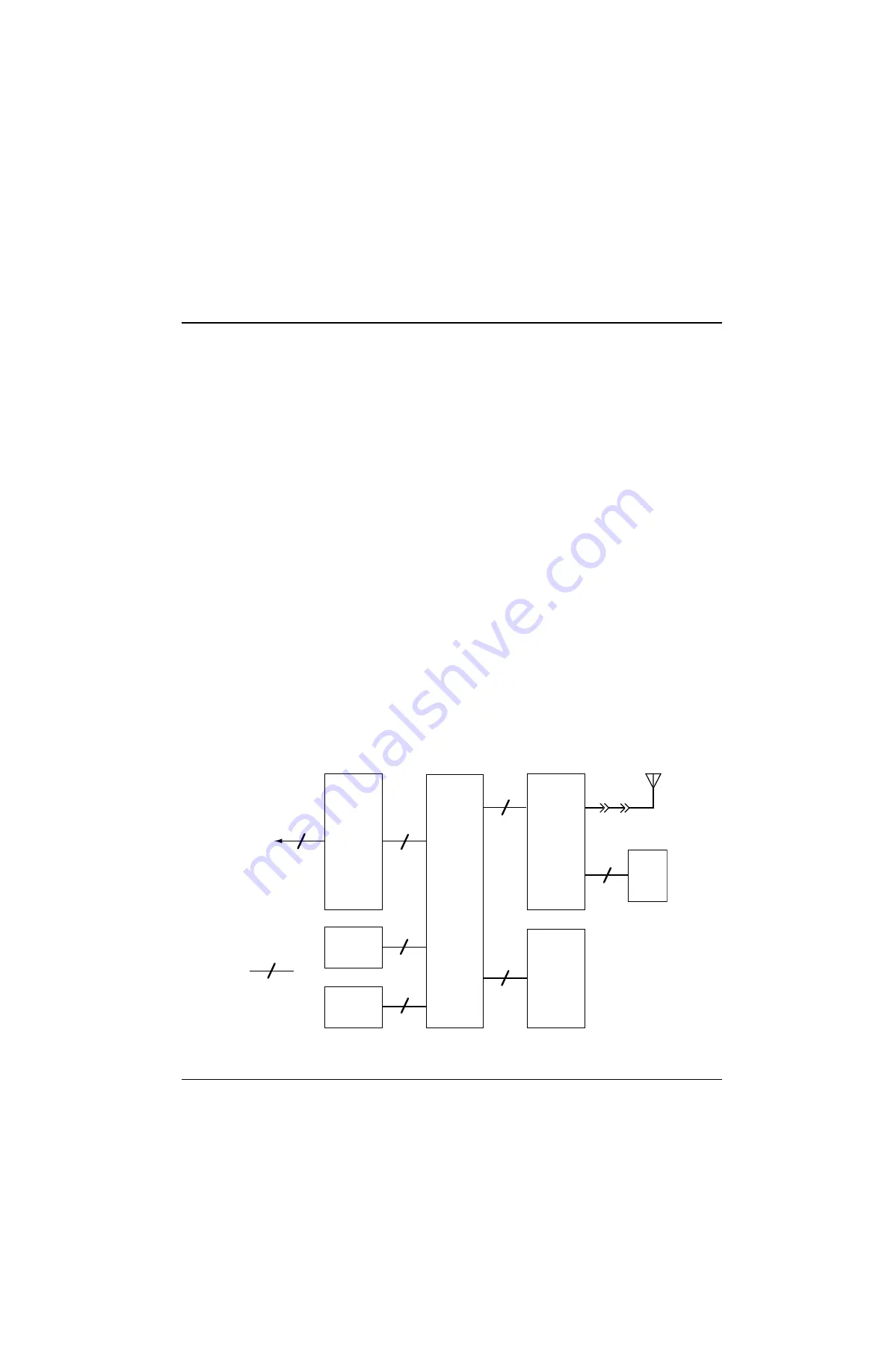
The ASTRO XTS 5000 radio (
) consists of the following:
• Band-dependent transceiver (RF) board
• Vocoder/controller (VOCON) board
• Universal flex assembly
• Display and keypad assemblies (Models II and III only)
• Encryption board (secure models only)
Universal
Flex
External
Accessory
Connector
(Side Connector,
Controls, LEDs,
Speaker,
Microphone)
Note:
indicates 26
wires
VOCON
Board
Transceiver
Board
Encryption
Module
(Optional)
7.5V
Battery
Keypad
Antenna
Display
3
26
40
22
26
22
40
13
J301
J107
J701
J101
P1
J1
P101
P201
J2
J3
MAEPF-27277-O
Summary of Contents for ASTRO XTS-5000
Page 7: ...vi Table of Contents November 16 2006 6881094C31 E Notes ...
Page 11: ...x List of Figures November 16 2006 6881094C31 E Notes ...
Page 17: ...November 16 2006 6881094C31 E xvi CommercialWarranty Notes ...
Page 31: ...November 16 2006 6881094C31 E xxx Portable Radio Model Numbering System Notes ...
Page 83: ...November 16 2006 6881094C31 E 3 44 Theory of Operation Encryption Module ...
Page 135: ...November 16 2006 6881094C31 E 5 44 Troubleshooting Charts Secure Hardware Failure Notes ...
Page 175: ...November 16 2006 6881094C31 E 7 32 Troubleshooting Tables List of Board and IC Signals Notes ...
Page 367: ...November 16 2006 6881094C31 E Glossary 10 Notes ...
Page 373: ...Index 6 November 16 2006 6881094C31 E Notes ...


