6881094C31-E
November 16, 2006
Theory of Operation:
Transceiver Board
3-3
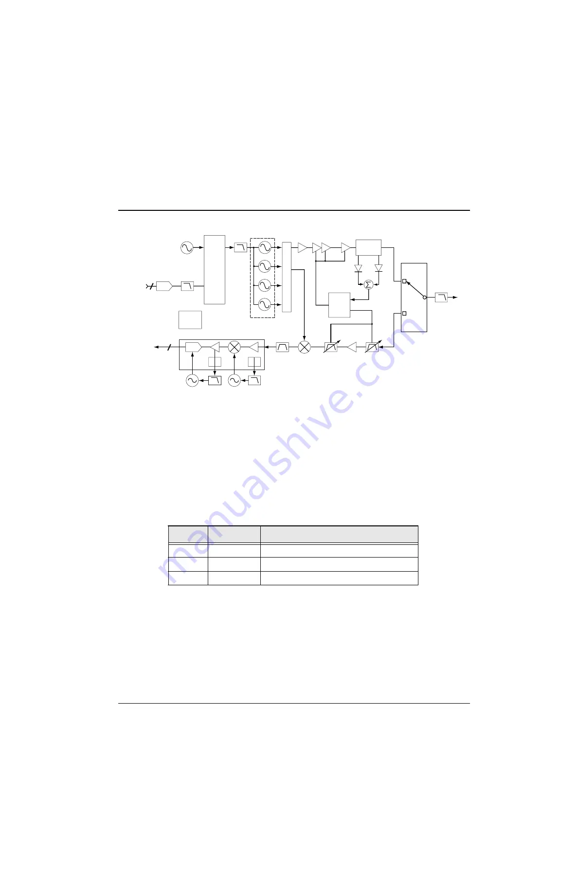
Figure 3-3. Transceiver (UHF Range 1, UHF Range 2 and 700–800 MHz) Block Diagram
(Power and Control Omitted)
3.1.1
Interconnections
This section describes the various interconnections for the transceiver board.
3.1.1.1 Battery Connector J3
Battery connector J3 consists of three gold-plated contacts on the printed circuit board that mate with
a B-plus connector assembly. Signal descriptions are in
3.1.1.2 VOCON Connector P1
VOCON connector P1 (located on the XCVR board) consists of 26 gold-plated pads for the 26-pin
compression connector, and one plated tool hole (pin 27) used for connector alignment. This is a
digital interface carrying DC power, control, and data between the XCVR and VOCON boards. P1
connects through the compression connector to P201 on the VOCON board.
Table 3-1. Battery Connector J3
Pin No.
Signal
Description
1
BATT
Battery positive terminal, nominally 7.5 Vdc
2
BSTAT
Battery status, from battery to VOCON
3
BAT_RTN
Battery negative terminal, tied to PCB ground
Reference
Oscillator
FracN
MOD
IN
Loop
Filter
LPF
FL200
Y200
DAC
U203
VCO 1
VCOBIC
VCO 2
Crystal
Filter
Mixer
2ND
LO
Sample
Clk
RX_SSI to
VOCON Board
TX_SSI from
VOCON Board
Preselector
Filter
PCIC
U104
Power
Module
TX
Buffer
TX Driver
Amplifier
U102
D101
D102
U106
Directional
Coupler
U101
Antenna
Switch
Preselector
Filter
RX LNA
To
Antenna
Harmonic
Filter
Serial EE
PROM
U4
ABACUS III U500
MAEPF-27530-A
VCO 3
VCO 4
3
3
Note:
700/800 MHz has 3 VCO's (2 TX/RX, 1 TX)
UHF Range 1, has 4 VCO's (2 TX, 2 RX)
UHF Range 2, has 3 VCOs (2 Rx, 1 TX)
See
Note
Summary of Contents for ASTRO XTS-5000
Page 7: ...vi Table of Contents November 16 2006 6881094C31 E Notes ...
Page 11: ...x List of Figures November 16 2006 6881094C31 E Notes ...
Page 17: ...November 16 2006 6881094C31 E xvi CommercialWarranty Notes ...
Page 31: ...November 16 2006 6881094C31 E xxx Portable Radio Model Numbering System Notes ...
Page 83: ...November 16 2006 6881094C31 E 3 44 Theory of Operation Encryption Module ...
Page 135: ...November 16 2006 6881094C31 E 5 44 Troubleshooting Charts Secure Hardware Failure Notes ...
Page 175: ...November 16 2006 6881094C31 E 7 32 Troubleshooting Tables List of Board and IC Signals Notes ...
Page 367: ...November 16 2006 6881094C31 E Glossary 10 Notes ...
Page 373: ...Index 6 November 16 2006 6881094C31 E Notes ...


