6871620L01-C
May 28, 2008
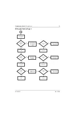
Troubleshooting Charts:
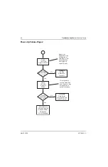
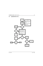
Top/Side Button Test
5-15
5.8
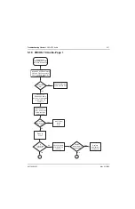
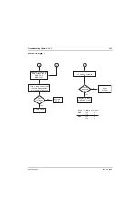
Top/Side Button Test
Verify operation
of zone knob
using Button Test
flowchart
Top/Side Button
Test
Yes
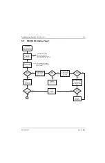
Using RSS, verify
problem button is
enabled for
function
No
Button check
OK?
Buttons
enabled?
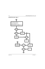
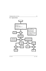
Using a voltmeter, measure the
voltage at U1305 pin 3 while
depressing the following buttons:
Emergency, Side Button 1,
Side Button 2, and Side Button 3.
The probe points are as follows:
Emergency Button 0.03V
Clear/Secure Button 1.40V
Programmable Button 2.20V
No Button Pressed 2.85V
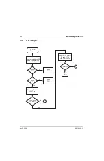
Synopsis
This chart relates ro a failure in
reading the buttons: Emergency,
Side Button 1, Side Button 2, or
SIde Button 3.
Basic failure modes are as follows:
1) Failure in controls flex circuit
2) Bad connection
3) Defective Switch
4) Defective A/D port in GCAP II
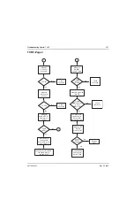
Yes
Yes
No
Use RSS
to enable
button
Levels
Correct?
Replace U1305
No
No
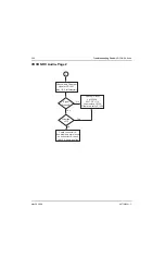
Verify physical
operation of
buttons
Buttons
OK?
Replace Radio
Chassis Assembly
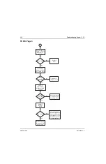
No
Verify connections
and Control Top/ PTT
flex circuit and repair
as necessary
Yes
Problem
Fixed?
End
Yes
Replace
U1304
Summary of Contents for ASTRO XTSTM 4000
Page 1: ...COLOR CHORDS 7 ASTRO XTSTM 4000 Portable Radio Detailed Service Manual ...
Page 2: ......
Page 16: ...May 28 2008 6871620L01 C xiv Commercial Warranty Notes ...
Page 22: ...May 28 2008 6871620L01 C 1 6 Introduction Notes ...
Page 26: ...May 28 2008 6871620L01 C 2 4 Radio Power Notes ...
Page 56: ...May 28 2008 6871620L01 C 3 30 Theory of Operation Notes ...
Page 100: ...May 28 2008 6871620L01 C 6 8 Troubleshooting Waveforms Notes ...
Page 194: ...May 28 2008 6871620L01 C B 2 Motorola Service Centers Notes ...
Page 204: ...May 28 2008 6871620L01 C Glossary 10 Glossary Notes ...
Page 209: ......

