List of Figures
vii
6871620L01-C
May 28, 2008
List of Figures
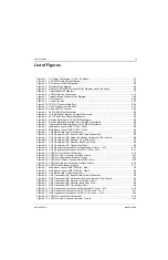
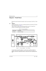
Figure 2-1. DC Power Distribution – VHF/ UHF Radio............................................................................ 2-1
Figure 3-1. XTS 4000 Overall Block Diagram ......................................................................................... 3-1
Figure 3-2. RF Transceiver Block Diagram ............................................................................................. 3-2
Figure 3-3. Receiver Block Diagram ....................................................................................................... 3-4
Figure 3-4. Abacus III (AD9864) Functional Block Diagram (from data sheet) ....................................... 3-6
Figure 3-5. Transmitter Block Diagram ................................................................................................... 3-7
Figure 3-6. VOCON Section Connections............................................................................................. 3-13
Figure 3-7. Patriot EIM and Memory Block Diagram............................................................................. 3-18
Figure 3-8. CE Connector ..................................................................................................................... 3-23
Figure 3-9. Control Top Flex.................................................................................................................. 3-25
Figure 3-10. VOCON Transmit Audio Path ............................................................................................. 3-26
Figure 3-11. VOCON Receive Audio Path .............................................................................................. 3-27
Figure 3-12. Radio ON/OFF Circuitry...................................................................................................... 3-28
Figure 6-1. 24.576 MHz Clock Waveform ............................................................................................... 6-2
Figure 6-2. 16.8 MHz Buffer Input and Output Waveforms ..................................................................... 6-3
Figure 6-3. 32.768 kHz Clock Outputs Waveforms ................................................................................. 6-4
Figure 6-4. Receive Serial Audio Port (SAP) Waveforms ....................................................................... 6-5
Figure 6-5. Receive Baseband Interface Port (RX BBP) Waveforms ..................................................... 6-6
Figure 6-6. Transmit Baseband Interface Port (TX BBP) Waveforms ..................................................... 6-7
Figure 8-1. Main Board Layout (NUD7115B) – Side 1 ............................................................................ 8-2
Figure 8-2. Main Board Layout (NUD7115B) – Side 2 ............................................................................ 8-3
Figure 8-3. VHF Main Board Overall Schematic ..................................................................................... 8-4
Figure 8-4. VHF Transceiver (RF) Board Overall Circuit Schematic....................................................... 8-5
Figure 8-5. VHF Transceiver (RF) Antenna Switch and Harmonic Filter Circuits ................................... 8-6
Figure 8-6. VHF Transceiver (RF) Receiver Front End Circuit................................................................ 8-7
Figure 8-7. VHF Transceiver (RF) Receiver Back End Circuit ................................................................ 8-8
Figure 8-8. VHF Transceiver (RF) Transmitter Circuit ............................................................................ 8-9
Figure 8-9. VHF Frequency Generation Unit (Synthesizer) Circuit – 1 of 2 .......................................... 8-10
Figure 8-10. VHF Frequency Generation Unit (VCO) Circuit – 2 of 2 ..................................................... 8-11
Figure 8-11. VOCON: Overall Circuit Schematic .................................................................................... 8-12
Figure 8-12. VOCON: Audio, Connector Interface Circuits ..................................................................... 8-13
Figure 8-13. VOCON: Controller and Memory Circuits ........................................................................... 8-14
Figure 8-14. VOCON: DC Power, Clocks and ON/OFF Circuit............................................................... 8-15
Figure 8-15. VOCON: Audio and Accessory Interface Circuits ............................................................... 8-16
Figure 8-16. VOCON: Miscellaneous Circuits ......................................................................................... 8-17
Figure 9-1. Main Board Layout (NUE7350A/B) – Side 1......................................................................... 9-2
Figure 9-2. Main Board Layout (NUE7350A/B) – Side 2......................................................................... 9-3
Figure 9-3. UHF Main Board Overall Schematic ..................................................................................... 9-4
Figure 9-4. UHF Transceiver (RF) Board Overall Circuit Schematic....................................................... 9-5
Figure 9-5. UHF Transceiver (RF) Antenna Switch and Harmonic Filter Circuits ................................... 9-6
Figure 9-6. UHF Transceiver (RF) Receiver Front End Circuit ............................................................... 9-7
Figure 9-7. UHF Transceiver (RF) Receiver Back End Circuit................................................................ 9-8
Figure 9-8. UHF Transceiver (RF) Transmitter Circuit ............................................................................ 9-9
Figure 9-9. UHF Frequency Generation Unit (Synthesizer) Circuit – 1 of 3 .......................................... 9-10
Figure 9-10. UHF Frequency Generation Unit (TX VCO) Circuit – 2 of 3 ............................................... 9-11
Figure 9-11. UHF Frequency Generation Unit (RX VCO) Circuit – 3 of 3 ............................................... 9-12
Figure 9-12. VOCON: Overall Circuit Schematic .................................................................................... 9-13
Figure 9-13. VOCON: Audio, Connector Interface Circuits ..................................................................... 9-14
Summary of Contents for ASTRO XTSTM 4000
Page 1: ...COLOR CHORDS 7 ASTRO XTSTM 4000 Portable Radio Detailed Service Manual ...
Page 2: ......
Page 16: ...May 28 2008 6871620L01 C xiv Commercial Warranty Notes ...
Page 22: ...May 28 2008 6871620L01 C 1 6 Introduction Notes ...
Page 26: ...May 28 2008 6871620L01 C 2 4 Radio Power Notes ...
Page 56: ...May 28 2008 6871620L01 C 3 30 Theory of Operation Notes ...
Page 100: ...May 28 2008 6871620L01 C 6 8 Troubleshooting Waveforms Notes ...
Page 194: ...May 28 2008 6871620L01 C B 2 Motorola Service Centers Notes ...
Page 204: ...May 28 2008 6871620L01 C Glossary 10 Glossary Notes ...
Page 209: ......


