6871620L01-C
May 28, 2008
Theory of Operation:
Transceiver Section
3-5
The receiver front end consists of a pre-selector filter, an RF amplifier, a post-selector filter, mixer,
and an IF crystal filter. A switchable attenuator is also inserted between the antenna switch and the
pre-selector filter. The RF amplifier is a discrete RF transistor with associated circuitry. The mixer is a
double-balanced, active mixer IC, coupled by transformers. The receiver (RX) local oscillator (LO) is
provided by the FGU.
3.1.2.1.1 Pre-Selector and Post-Selector Filters
VHF/ UHF:
The receiver front end uses two discrete, tunable, bandpass filters to achieve its required
out-of-band rejection. The pre-selector filter precedes the RF amplifier, while the post-selector filter
follows the RF amplifier. DAC2, from the PCIC, is used to simultaneously tune both the pre-selector
and post-selector filters by applying voltage to the varactors.
3.1.2.1.2 LNA (Low-Noise Amplifier)
The XTS 4000 radio uses a discrete transistor for the low-noise amplifier Q430. A feedback network
between the collector and base improves stability and gain balance across the frequency band. Input
and output LC networks match the LNA impedance to 50 ohms.
A diode limiter D703 protects the amplifier damage by strong input signals.
3.1.2.1.3 Mixer
The mixer U470
down-converts the received RF to the first intermediate frequency (IF). The I
F is 44.85 MHz (VHF) and 73.35 MHz (UHF). High-side LO injection is used for the VHF whereas
low-side LO injection is used for the UHF. Transformers are used as baluns to convert signals from
single-ended to balanced at pins RFN and RFP. An output transformer converts the balanced signal
at pins IFN and IFP to a single-ended output.
3.1.2.1.4 IF Filter (Crystal Filter)
The IF filter FL490 is a leadless, surface-mount, 3-pole, quartz crystal filter. This narrow bandpass
filter gives the radio its adjacent-channel and alternate-channel rejection performance.
An input LC network matches the filter impedance to 50 ohms. The output match for the filter
matches the IF Filter output port to the ABACUS III input.
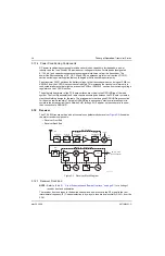
3.1.2.2 Receiver Back End
The receiver back end, which consists of the Abacus III (AD9864 IF digitizing subsystem) IC and its
associated circuitry, processes the down-converted IF signal to produce digital data for final
processing by the VOCON DSP.
NOTE:
Table 8.1, “List of Schematics and Boards Overlays,” on page 8-1
for a listing of
receiver back end schematics.
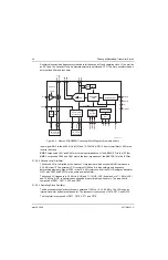
3.1.2.2.1 Abacus III IC U500
The AD9864 (
) is a general-purpose, IF subsystem that digitizes a
low-level 10–300 MHz IF input with a bandwidth up to 270 kHz. The output of the Abacus III IC is SSI
data to the VOCON.
The signal chain of the AD9864 consists of a low-noise amplifier, a mixer, a bandpass sigma-delta
A/D converter, and a decimation filter with programmable decimation factor. An automatic gain
control (AGC) circuit provides the AD9864 with 12 dB of continuous gain adjustment. The high
dynamic range and inherent anti-aliasing provided by the bandpass sigma-delta converter allow the
AD9864 to cope with blocking signals 80 dB stronger than the desired signal.
Summary of Contents for ASTRO XTSTM 4000
Page 1: ...COLOR CHORDS 7 ASTRO XTSTM 4000 Portable Radio Detailed Service Manual ...
Page 2: ......
Page 16: ...May 28 2008 6871620L01 C xiv Commercial Warranty Notes ...
Page 22: ...May 28 2008 6871620L01 C 1 6 Introduction Notes ...
Page 26: ...May 28 2008 6871620L01 C 2 4 Radio Power Notes ...
Page 56: ...May 28 2008 6871620L01 C 3 30 Theory of Operation Notes ...
Page 100: ...May 28 2008 6871620L01 C 6 8 Troubleshooting Waveforms Notes ...
Page 194: ...May 28 2008 6871620L01 C B 2 Motorola Service Centers Notes ...
Page 204: ...May 28 2008 6871620L01 C Glossary 10 Glossary Notes ...
Page 209: ......

