May 28, 2008
6871620L01-C
3-8
Theory of Operation:
Transceiver Section
3.1.3.3 Power Amplifier Transistor Q107
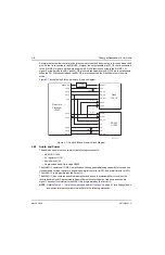
The power amplifier transistor, Q107, is an LDMOS FET housed in a high-power, surface-mount
package. To prevent thermal damage, it is essential that the heat sink of the power module be held in
place against the radio chassis. The input impedance-matching network uses discrete inductors and
capacitors. The low-pass output matching network uses lumped LCs. Drain bias is applied through
E101, R130 and L105. Gain is dynamically controlled by adjusting the gate bias. The gate is
insulated from the drain and source so that gate bias current is essentially zero. Gate bias is applied
through R102, R105, and R106.
VHF:
The input and output impedance-matching networks consist of C112–C115, C120–C124,
L103–L104, L106–L108.
UHF:
The input and output impedance-matching networks consist of C114, C120–C122, C124,
C141, L108 and L113.
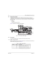
3.1.3.4 Antenna Switch
NOTE:
Refer to
Table 8.1, “List of Schematics and Boards Overlays,” on page 8-1
for a listing of
schematics that will aid in the following discussion.
The antenna switch is a single-pole, double-throw, positive-intrinsic-negative (PIN) diode, transmit/
receive (T/R) antenna switch. Forward DC bias (via Q104) turn the diodes ON, reverse or zero bias
turns them OFF.
VHF:
PIN diodes D707 and D717 form a narrow-band, quarter-wave, T/R switch.
UHF:
PIN diodes D701 and D702 form a narrow-band, quarter-wave, T/R switch.
In transmit mode, both diodes are forward-biased, and the signal goes from the transmitter to the
antenna through the low resistance of the series PIN diode, while the low resistance of the shunt
diode shorts the receiver. In receive mode, neither diode is biased and both behave as small-value
capacitors, creating a high blocking impedance, in effect disconnecting the transmitter circuitry from
the antenna.
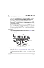
3.1.3.5 Harmonic Filter
The harmonic filter is a high-power, low-loss, low-pass filter. Its purpose is to suppress transmitter
harmonics. The filter also improves receiver out-of-band rejection. Shield SH07 must be in place to
achieve the required stop band rejection. The harmonic filter uses discrete components.
VHF:
The pass band is up to 190 MHz, and the stop band is above 260 MHz.
UHF:
The pass band is up to 490 MHz, and the stop band is above 760 MHz.
Summary of Contents for ASTRO XTSTM 4000
Page 1: ...COLOR CHORDS 7 ASTRO XTSTM 4000 Portable Radio Detailed Service Manual ...
Page 2: ......
Page 16: ...May 28 2008 6871620L01 C xiv Commercial Warranty Notes ...
Page 22: ...May 28 2008 6871620L01 C 1 6 Introduction Notes ...
Page 26: ...May 28 2008 6871620L01 C 2 4 Radio Power Notes ...
Page 56: ...May 28 2008 6871620L01 C 3 30 Theory of Operation Notes ...
Page 100: ...May 28 2008 6871620L01 C 6 8 Troubleshooting Waveforms Notes ...
Page 194: ...May 28 2008 6871620L01 C B 2 Motorola Service Centers Notes ...
Page 204: ...May 28 2008 6871620L01 C Glossary 10 Glossary Notes ...
Page 209: ......

