Overview 2-7
BLE100 Installation and Operation Manual
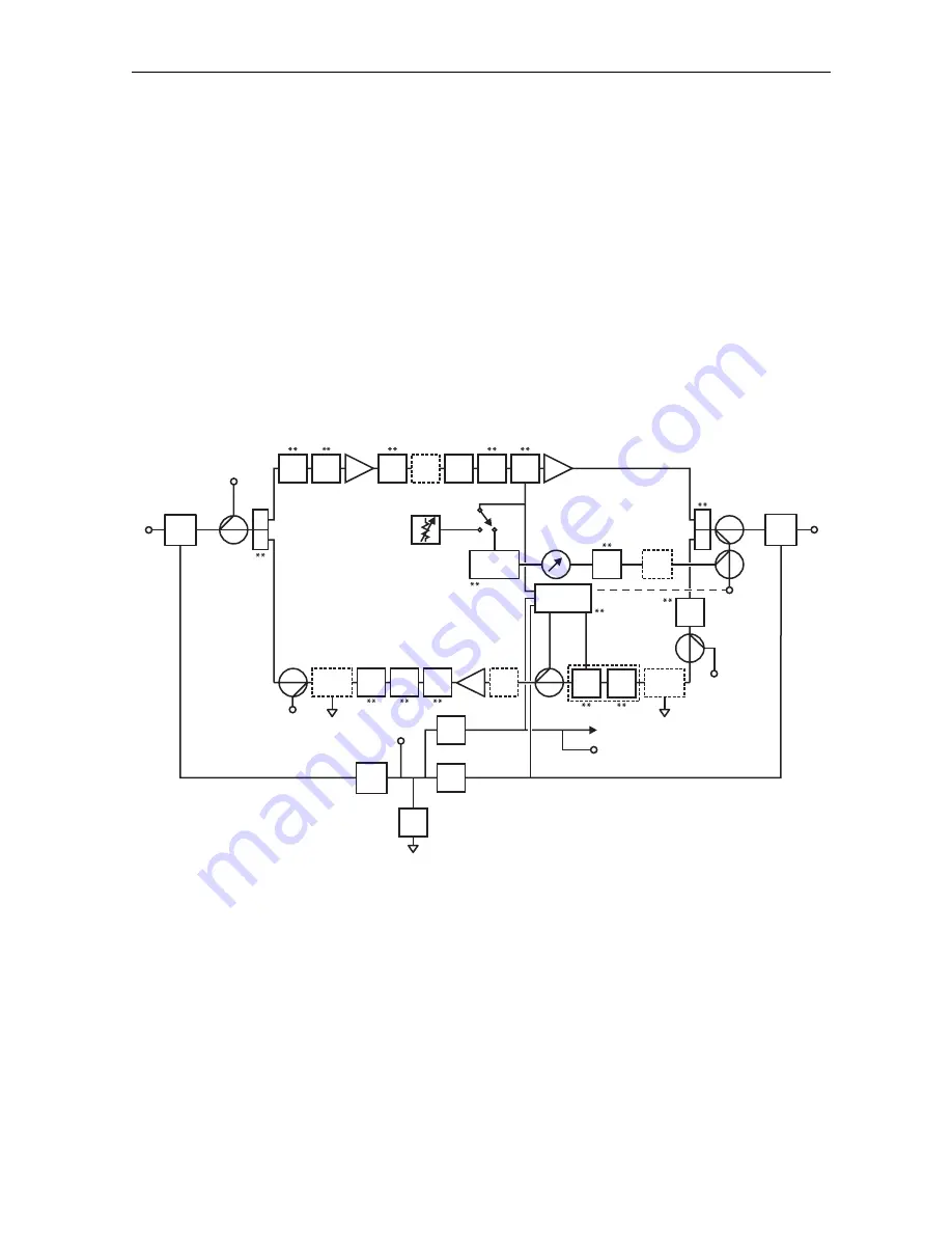
Forward Path
The operational gain of the BLE100 amplifiers is 34 dB with 16 dB of return loss. The operating
gain includes provisions for the insertion loss of the input cable equalizer and required reserve
gain to operate the Bode equalizer in the middle of its range. The low-noise figure, pre-amplifier
stage, is a 1 GHz hybrid followed by a power-doubled output stage. Between the two stages is a
JXP-*B pad socket, the Bode board, and the flatness and equalizer board. Because these losses
are located interstage, the noise figure is only significantly impacted by the insertion loss of the
forward cable equalizer or broadband cable simulator, and the input pad if its value is increased
from zero.
Figure 2-7 illustrates the interconnection among these components:
Figure 2-7
BLE100 block diagram
24 Vdc
DC test point
Power
supply
Input
port
JXP-B
-16 dB
JXP-B
LPF
BODE
RC
Therm
PP
PD
TP
-20 dB
AC test
point
JXP-B
Manual
LDR
H
L
-20 dB
TP
Auto
ICS
JXP
TP
-20 dB
Power
Block
Jumper
** Plug-in module
FTEC
Status
monitor
Surge
protector
Surge
protector
SFE
or
SCS
JXP-B
-
-1.0 dB
-1.0 dB
-1.0 dB
28 dB
-6.5 dB
-1.0 dB
-1.0 dB
-1.0 dB
SRE
-0.5 dB
+30.0 dB -0.3 dB
-0.4 dB
-0.4 dB
-0.4 dB
RF
RF/
AC
AC
-1.7
dB F
-1.0
dB R
23 dB
TP
Return
injection point
-20 dB
OnBrd
Atten
~ -3 dB
Output
port
H
L
RF/
AC
AC
RF
-1.7
dB F
-1.0
dB R
JXP-B
OnBrd
Atten
ADU/
TDU
Fuse
Return Path
The circuit board of the BLE100 includes the return path. This equips the BLE100 to pass
signals in the return or upstream direction. The standard circuit board contains all components
including the diplex filters with extended return bandwidth for the amplifier input and output.
Optional SRE-*-* return equalizers compensate for cable attenuation and are available in 1 dB
increments for S-split, and 2 dB increments for all other splits, from 0 dB through 12 dB.


