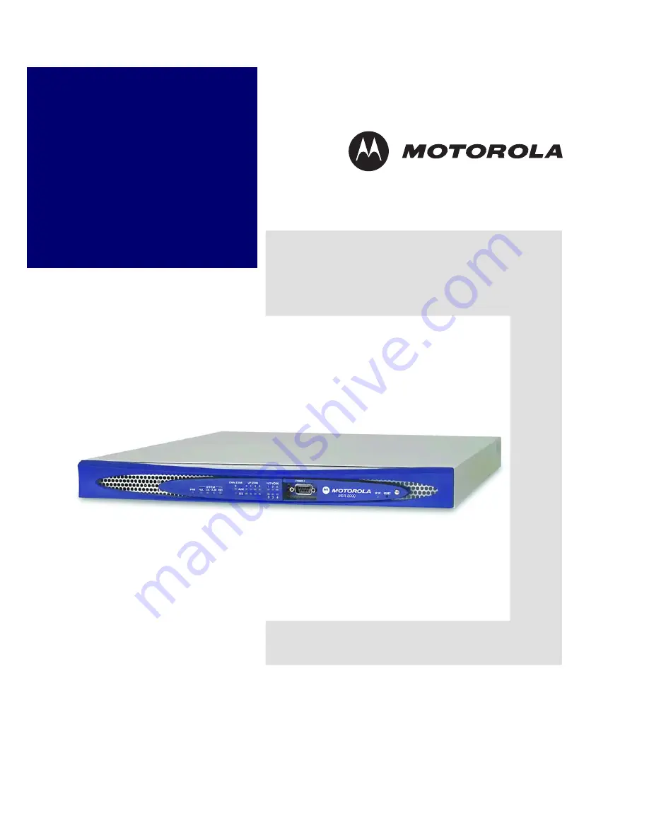
background image

BSR 2000 
Installation Guide

526359-001
Release 1.0
MGBI

Summary of Contents for BSR 2000

Page 1: ...BSR 2000 Installation Guide 526359 001 Release 1 0 MGBI ...

Page 2: ...ation of such revision or change Motorola provides this guide without warranty of any kind either implied or expressed including but not limited to the implied warranties of merchantability and fitness for a particular purpose Motorola may make improvements or changes in the product s described in this manual at any time Motorola and the stylized M logo are registered trademarks of Motorola Inc Br...

Page 3: ...ecte n est disponible veuillez appeler le Service clientèle de Motorola qui vous apportera son assistance Umweltschutz durch Recycling Wenn Sie dieses Zeichen auf einem Produkt von Motorola sehen entsorgen Sie das Produkt bitte nicht als gewöhnlichen Haus oder Büromüll Recycling bei Geräten von Motorola Bitte entsorgen Sie dieses Produkt nicht als gewöhnlichen Haus oder Büromüll In einigen Ländern...

Page 4: ...y zbierania odpadów elektrycznych i elektronicznych informacje o utylizacji należy uzyskać od biura obsługi klienta firmy Motorola Motorola Customer Service Beskyttelse af miljøet med genbrug Når du ser dette symbol på et Motorola produkt må produktet ikke bortskaffes sammen med husholdning saffald eller erhvervsaffald Genbrug af dit Motorola udstyr Dette produkt må ikke bortskaffes sammen med hus...

Page 5: ...latba a helyi hatóságokkal a lakóhelyén alkalmazott gyakorlattal kapcsolatos információért Amennyiben gyûjtõrendszer nem elérhetõ hívja a Motorola Ügyfélszolgálatot segítségért Kujdesja per ambientin rrethues me ane te perdorimit te perseritur Neqoftese shikoni kete simbol ne produktin Motorola mos e hidhni tej produktin duke prishur keshtu ambi entin e duke shkaktuar humbje komerciale Perdorimi i...

Page 6: ... Motorola Motorola Motorola Motorola Motorola Motorola Motorola Motorola Motorola ...

Page 7: ...t dangerous voltage levels are present within the equipment These voltages are not insulated and may be of sufficient strength to cause serious bodily injury when touched The symbol may also appear on schematics The exclamation point within an equilateral triangle is intended to alert the user to the presence of important installation servicing and operating instructions in the documents accompany...

Page 8: ...t is recommended that the customer install an AC surge arrestor in the AC outlet to which this device is connected This is to avoid damaging the equipment by local lightning strikes and other electrical surges This equipment operates over the marked Voltage and Frequency range without requiring manual setting of any selector switches Different types of line cord sets may be used for connections to...

Page 9: ...s connected Consult the dealer or an experienced radio TV technician for help You may find the following booklet prepared by the Federal Communication Commission helpful How to Identify and Resolve Radio TV Interference Problems Stock No 004 000 0342 4 U S Government Printing Office Washington DC 20402 Changes or modification not expressly approved by the party responsible for compliance could voi...

Page 10: ...formance of procedures other than those specified herein may result in hazardous radiation exposure Declaration of Conformity We Motorola Inc 111 Locke Drive Marlborough MA 01752 U S A declare under our sole responsiblity that the Broadband Services Router Model BSR 2000 to which this declaration relates is in conformity with one or more of the following standards EMC Standards EN 300 386 V 1 3 1 ...

Page 11: ...089 CORE 1999 and complies with the following specifications Safety UL 60950 1 1st Edition 2003 CSA 22 2 No 60950 1 03 1st Edition 2003 EN 60950 1 1st Edition 2002 IEC 60950 1 1st Edition 2001 EN 60825 1 2002 EN 60825 2 2000 EN 60950 2 2000 IEC 60825 1 Edition 1 2 2001 IEC 60825 2 Edition 2 2002 CDRH 21 CFR 1040 10 and 1040 11 ...

Page 12: ...2004 Class B CISPR 22 1997 A1 2000 A2 2002 Class B AS NZ CISPR 22 2002 Class B Korean MIC Notice 2005 82 2005 Class B Immunity EN 300 386 V1 3 1 2001 EN 55024 2003 CISPR 24 2002 Korean MIC Notice 2005 83 2005 Environmental The BSR 2000 is designed to meet the following specifications EN 300 019 EN 300 119 GR 63 CORE 1995 ...

Page 13: ... Overview 2 1 Preinstallation Tasks 2 2 Installation Accessories 2 2 Required Tools and Equipment 2 2 Inspecting the Installation Site 2 3 Site Installation Options 2 3 Equipment Rack Choices 2 3 Mounting the BSR 2000 in an Equipment Rack 2 4 Rack Mounting Options 2 4 Before You Begin 2 4 Rack Mounting Procedure 2 4 Marking the Installation Location on the Equipment Rack 2 4 Attaching the Mounting...

Page 14: ...es to the BSR 2000 2 14 Connecting a Coaxial Cable to the Downstream Channel Port 2 14 Connecting Coaxial Cables to the Upstream Channel Ports 2 14 Connecting a Coaxial Cable to the Wireless Port 2 15 Setting up a Console Monitor 2 16 Configuring Communications Parameters 2 17 Connecting a Console Monitor 2 17 Replacing the Compact Flash Memory Card 2 18 Connecting the BSR 2000 to a Power Source 2...

Page 15: ...r B 4 T1 E1 BITS Connector B 5 Redundant Port Connector B 6 C Safety Warnings Cautions and Guidelines Overview C 1 Safety Warnings and Cautions C 1 Qualified Personnel Caution C 2 Installation Warning C 2 Rack Mounting Caution C 2 Stacking Caution C 2 SELV Circuit Warning C 2 Operating Temperature Caution C 3 Electrical Safety Warning C 3 Electrical Grounding Warning C 3 Grounded Equipment Warning...

Page 16: ...BSR 2000 Installation Guide xvi MGBI 526359 001 Jewelry Removal Caution C 4 Safety Guidelines C 5 Electrical Safety Guidelines C 6 In Case of Electrical Accident C 6 Index ...

Page 17: ...ce the BSR 2000 Documentation Set The following documents comprise the BSR 2000 documentation set BSR 2000 Installation Guide This document describes how to install the BSR 2000 product BSR 2000 Configuration and Management Guide This document provides the instructions and procedures for configuring and managing the BSR 2000 BSR 2000 Command Reference Guide This document contains descriptions of t...

Page 18: ...ngle brackets ping ip address ping 54 89 145 71 Arguments in italic and enclosed by angle brackets must be replaced by the text the argument represents In the example 54 89 345 71 replaces ip address When entering the argument do not type the angle brackets bar brackets disable level Bar brackets enclose optional arguments The example indicates you can use the disable command with or without speci...

Page 19: ...en entering the parameter do not type the vertical bar or the brace brackets Note A note contains tips suggestions and other helpful information such as references to material not contained in the document that can help you complete a task or understand the subject matter Caution The exclamation point within an equilateral triangle is intended to alert the user to the presence of important install...

Page 20: ...otorola Technical Response Center TRC The TRC is on call 24 hours a day 7 days a week In addition Motorola Online offers a searchable solutions database technical documentation and low priority issue creation and tracking U S 1 888 944 HELP 1 888 944 4357 International 215 323 0044 WWW http broadband motorola com noflash websupport html ...

Page 21: ...cification DOCSIS 2 0 and PacketCable 1 0 standards It provides two Gigabit and four autosensing 10 100 BASE T Ethernet ports for network access one 10 100 BASE T port for redundancy support one T1 E1 port for BITS recovery and four upstream channels and one downstream channel for DOCSIS connectivity The BSR 2000 enables Multiple System Operators MSOs to expand their service area and deliver the t...

Page 22: ...EDs for downstream port LEDs for upstream ports System LEDs R W LED Reset button Network LEDs RS 232 console port Flash card cover Rear View US2 US1 US0 DS0 IF 1 0 2 3 5 4 T1 E1 BITS connector 10 100 Ethernet ports Redundant 10 100 port GIG E SFP ports Wireless connector Downstream port Type F connector AC power receptacle Power switch Power Status LED Upstream ports Type F connector US3 bsr2k019 ...

Page 23: ...ng the Installation Site Site Installation Options Mounting the BSR 2000 in an Equipment Rack Setting up the BSR 2000 for Desktop Operation Connecting Network Cables Setting up a Console Monitor Replacing the Compact Flash Memory Card Connecting the BSR 2000 to a Power Source Determining Successful Booting Interpreting LED Displays Rebooting the System ...

Page 24: ...ck mount or desktop installation procedures you need the following items Motorola does not provide these items you must obtain them yourself A 2 Phillips screwdriver for rack mount installations only A terminal or PC with terminal emulation software A shielded RS 232 crossover cable with a female DB 9 pin connector and a connector compatible with the RS 232 port on the terminal or PC Ethernet patc...

Page 25: ...s When setting up the BSR 2000 for desktop operation confirm that the desktop is flat level and stable and can support 20 lbs 9 kg Also confirm that power and network cables connected to the BSR 2000 will run in areas that will be undisturbed during operation Site Installation Options The BSR 2000 offers the following site installation options Mounting in an equipment rack front mount or mid mount...

Page 26: ...quipment rack perform the following tasks 1 Mark the location on the rack where you intend to mount the BSR 2000 2 Attach the mounting brackets to the sides of the BSR 2000 chassis 3 Mount and secure the BSR 2000 in its equipment rack The following sections describe these tasks Marking the Installation Location on the Equipment Rack The BSR 2000 is a 1U height device that is designed to straddle t...

Page 27: ...acket holes with the threaded holes at the position for the mounting option you selected Be sure to use the left bracket on the left side of the BSR 2000 and the right bracket on the right side of the BSR 2000 2 Insert screws through the rack mounting holes into the threaded holes on the side of the BSR 2000 3 Tighten the screws with a Phillips screwdriver bsr2k040 Right mounting bracket Left moun...

Page 28: ...2000 mounting bracket holes with the mounting holes of the equipment rack 2 Secure the BSR 2000 in the equipment rack Note Motorola recommends that you use two people to perform the rack mounting procedure One person should hold the BSR 2000 in position while the other secures it in the equipment rack bsr2k003 Mid Mount Front Mount STS DOWNSTREAM UPSTREAM NETWORK ALM 0 1 1 0 2 3 2 3 5 4 0 SYSTEM P...

Page 29: ...l and secure Capable of supporting 20 lbs 9 kg Before You Begin Before you operate the BSR 2000 on a desktop make sure of the following You have all tools and other items required to complete the installation including the four rubber feet found in one of the BSR 2000 accessory bags You are wearing an antistatic wrist strap or foot strap bsr2k016 Mid Mount Front Mount STS DOWNSTREAM UPSTREAM NETWO...

Page 30: ...SR 2000 in its intended location on the desktop Figure 2 4 Attaching Rubber Feet to the Bottom of the BSR 2000 Enclosure Connecting Network Cables You connect the following kinds of cables to the BSR 2000 A shielded DB 9 console cable Shielded Twisted Pair STP Ethernet cables equipped with shielded RJ 45 plugs Ethernet cables equipped with LC type fiber optic plugs One coaxial cable for the BSR 20...

Page 31: ...ed 0 1 2 and 3 as shown in Figure 2 5 Figure 2 5 RJ 45 Ethernet Ports To connect the BSR 2000 to the network follow these steps 1 Connect a male shielded RJ 45 connector at one end of the cable to the assigned Ethernet port on the router hub or switch 2 Connect a male RJ 45 connector at the opposite end of the network cable to one of the four RJ 45 Ethernet ports on the BSR 2000 Note To maintain r...

Page 32: ...dicated 10 100BASE T Ethernet link The redundant port is labeled RED and is color coded in black To connect a cable to the redundant port follow these steps 1 Connect a male shielded RJ 45 connector to the redundant Ethernet port See Figure 2 6 2 Connect the opposite end of the network cable to the redundant Ethernet port on the second BSR 2000 Figure 2 6 Connecting a Cable to the Redundant 10 100...

Page 33: ... a Gigabit Ethernet port follow these steps 1 Remove the EMI plug from the SFP port by depressing the spring loaded latch and pulling the plug straight out of the port as shown in Figure 2 7 The EMI plug comes factory installed Save the EMI plug just in case you need to use it again in the future 2 Install an SFP module into one of the slots of the SFP cage until it clicks into place See Figure 2 ...

Page 34: ...le in the remaining Gigabit Ethernet port and connect cables to it Note To maintain regulatory compliance use only Motorola tested and approved SFP modules Refer to the price catalog for available modules Note The BSR 2000 utilizes LC connectors for its optical interfaces To interface with equipment that utilizes SC connectors you will need to use the appropriate LC SC cables or adapters Refer to ...

Page 35: ...eference from either a T1 or E1 based BITS source The BITS port color coded with a gold label uses a shielded RJ 48 connector with a Shielded Twisted Pair STP cable To connect a cable to the BITS interface follow these steps 1 Connect a male RJ 48 connector to the BITS interface port See Figure 2 9 2 Connect the opposite end of the network cable to a T1 or E1 based BITS source bsr2k024 To Ethernet...

Page 36: ...ownstream channel connector DS0 on the BSR 2000 rear panel The port is color coded with an orange label 2 Insert the center conductor of the downstream channel cable into the small opening at the center of the BSR 2000 downstream channel connector 3 Secure the connection by screwing the outside cable connector housing onto the BSR 2000 downstream connector until finger tight then using a wrench ti...

Page 37: ...sing onto the BSR 2000 upstream connector until finger tight then using a wrench tighten the connector one quarter turn 15 in lbs when using a torque wrench Figure 2 10 Connecting Upstream and Downstream Cables to the BSR 2000 Rear Panel Connecting a Coaxial Cable to the Wireless Port The BSR 2000 features a wireless port to provide IF output on the rear panel The port is color coded with a green ...

Page 38: ...necting a Cable to the Wireless Port Setting up a Console Monitor You must connect a terminal or a PC with terminal emulation software to the BSR 2000 to perform the following tasks Supply the BSR 2000 with an IP address Configure the BSR 2000 if you choose not to use a Telnet session To connect a console monitor to the BSR 2000 and communicate with it complete the following tasks Note To supply t...

Page 39: ...ted in Table 2 1 Connecting a Console Monitor To connect a terminal or PC to the BSR 2000 follow these steps and refer to Figure 2 12 1 Connect one end of a shielded RS 232 crossover null modem cable to the RS 232 port on the terminal or PC 2 Connect the other end of the shielded cable with the female DB 9 pin connector to the male DB 9 pin connector labeled Console Port on the front panel of the ...

Page 40: ...lash memory card follow these steps 1 Remove the flash card cover by using a flat head screwdriver to loosen the captive screw See Figure 2 13 The flash card cover swings out towards you 2 Push the ejector button located to the left of the flash card connector See Figure 2 14 3 Pull the flash card straight out of the connector See Figure 2 14 The flash card cover was designed to double as a remova...

Page 41: ...he card up properly with the connector it is keyed and can only be inserted one way 5 Push the card in firmly until it seats into the connector 6 Replace the flash card cover and tighten the captive screw to secure it Figure 2 13 Removing the Flash Card Cover BSR 2000 CONSOLE R W RESET bsr2k026 R W LED ...

Page 42: ...on AC power that it receives through an autoranging power supply The circuit to which you connect the BSR 2000 must provide power within the following range 100 240 VAC Figure 2 15 shows the power cord connection to the BSR 2000 Hooks Compact flash memory card Ejector button BSR 2000 CONSOLE R W RESET bsr2k027 Side View Flash Card Tab Flash Card Cover Hook ...

Page 43: ...ther end of the power cord to the AC power outlet 4 To apply power to the BSR 2000 press the BSR 2000 power switch to the On I position Figure 2 15 Connecting a Power Cable to the BSR 2000 Determining Successful Booting After powering on the BSR 2000 observe the LEDs on its front panel The LED display varies until the BSR 2000 is booted When the booting process completes the LEDs should display as...

Page 44: ...er Status LED Power LED The Power LED is a green LED located on the front panel as shown in Figure 2 16 The Power LED is lit when the BSR 2000 is connected to an AC power source and the power switch is in the On I position Figure 2 16 Power and System LEDs Note If the LEDs do not match the description in this section refer to Interpreting LED Displays in the next section STS DOWNSTREAM UPSTREAM NE...

Page 45: ...tus ALM Alarm RED Redundancy Interpretation Off Green Off Off Normal operating status Off Green Yellow Off Failure BSR 2000 is operating with an alarm condition Note This LED sequence occurs when an alarm condition is detected on individual upstream and downstream ports Yellow Off Off Off Indicates a possible hardware failure Yellow Off Yellow Off Failure BSR 2000 is not operating Yellow Green Yel...

Page 46: ...ndicate their operational status These LEDs are located near the center of the BSR 2000 front panel and are labeled STS Status and ALM Alarm as shown in Figure 2 18 Figure 2 18 Upstream and Downstream Port LEDs BSR 2000 CONSOLE R W RESET bsr2k034 R W LED STS DOWNSTREAM UPSTREAM NETWORK ALM 0 1 1 0 2 3 2 3 5 4 0 SYSTEM PWR FAIL STS ALM RED bsr2k037 Upstream and Downstream Port LEDs ...

Page 47: ...EDs labeled 0 through 3 correspond to the four 10 100 Ethernet ports The LEDs labeled 4 and 5 correspond to the two Gig E SFP ports Table 2 4 provides an interpretation of the LED display states Figure 2 19 Network LEDs Table 2 3 BSR 2000 Downstream and Upstream Port LED Display States STS Status ALM Alarm Interpretation Green Off Normal operating status Green Amber Operating with an alarm conditi...

Page 48: ...2 4 BSR 2000 Front Panel Network LED Display States Network LEDs Display State Interpretation 0 through 3 10 100 ports On steady indicates a working Ethernet connection Link exists between the BSR 2000 and the device at the other end of the physical connection On blinking indicates activity on the Ethernet port Off indicates that a connection to the device at the other end of the physical connecti...

Page 49: ... Ethernet Port LEDs for ports 4 and 5 the Gig E ports light under different conditions as their respective front panel Network LEDs Table 2 5 provides a definition of the LED display states Note The Gig E SFP Ports use only the outer two LEDs The other two LEDs are not used and will not illuminate under any conditions bsr2k043 Gig E SFP Port LEDs 2 3 4 5 1 Bits RED 0 10 100 Ethernet Port LEDs 10 1...

Page 50: ... 2000 and the device at the other end of the physical connection On blinking indicates activity on the Ethernet port Off indicates that a connection to the device at the other end of the physical connection is not established Gig E Ports 4 and 5 For copper based SFPs On indicates the presence of an SFP module Off indicates the absence of an SFP module For fiber based SFPs On indicates that an SFP ...

Page 51: ...Status LED The BSR 2000 provides a bi color green red status LED for the power supply located on the rear panel underneath the Power switch see Figure 2 22 Figure 2 22 BSR 2000 Power Status LED 0 1 2 3 4 5 T1 E1 BITS interface bsr2k038 BITS RED T1 E1 BITS LED bsr2k035 Power Status LED ...

Page 52: ...e RESET label and press the Reset button 2 Remove the tool Table 2 6 Status LED Display States LED Color Interpretation Green Power supply is operating within expected limits Red Indicates a problem with the power supply for example AC power failure DC output loss etc Note When the power is shut down or cycled the LED will momentarily turn red This is normal A steady red LED indicates a problem No...

Page 53: ...u press the Reset button the BSR 2000 reboots and the LEDs on the front panel display their boot sequence Where To Go From Here When you are sure that the BSR 2000 booted successfully go to the document BSR 2000 Configuration and Management Guide BSR 2000 CONSOLE R W RESET bsr2k033 Reset button ...

Page 54: ......

Page 55: ...ons Physical Electrical Environmental Network Interfaces SFP Module Specifications RF Spectrum Timing Generation Physical Form Factor 1U height Height 1 75 in 4 45 cm Width 19 in 48 26 cm with mounting brackets Chassis width 17 25 in 43 82 cm Depth 21 75 in 55 25 cm Fully configured weight 20 lbs 9 kg ...

Page 56: ...rnet SFP ports capable of accommodating either copper based or fiber based SFP modules Four shielded STP RJ 45 connector 10 100 Mbps Ethernet ports One additional shielded STP RJ 45 connector 10 100 BASE T port for redundancy support SFP Module Specifications This section provides specifications for the SFP modules Table A 1 1000BASE SX Multi Mode Fiber SFP Specifications Parameter Value Transmitt...

Page 57: ... 1000BASE EX Single Mode Fiber SFP Specifications Parameter Value Transmitter Type Longwave laser 1310 nm Range 40 Km Data Rate typical 1 250 Gbps Connector Duplex LC Regulatory Class 1 devices per FDA CDRH and IEC 825 1 laser safety regulations Table A 4 1000BASE ZX Single Mode Fiber SFP Specifications Parameter Value Transmitter Type Longwave laser 1550 nm Range 80 Km Data Rate typical 1 250 Gbp...

Page 58: ... RF output Downstream modulation QPSK for wireless DOCSIS operation 16 QAM for wireless DOCSIS operation 64 QAM 256 QAM Downstream output frequency range 88 857 MHz channel center Output frequency step size 125 KHz Wireless IF Support Output Frequency 44 MHz Timing Generation The BSR 2000 provides the capability to slave the CMTS clocks to the BITS interface network timing reference via the rear p...

Page 59: ...g connectors Console Port Connector 10 100 Ethernet Port Connectors Gigabit Ethernet Port Connector T1 E1 BITS Connector Redundant Port Connector Console Port Connector The Console Port connector shown in Figure B 1 is a male DB 9 pin connector Table B 1 provides the pin assignments pinouts for this connector ...

Page 60: ... Console Port Pin Assignments Pin Number Name Description Pin 1 CD Carrier Detect Pin 2 RXD Receive Data Pin 3 TXD Transmit Data Pin 4 N A Not used Pin 5 GND System Ground Pin 6 N A Not used Pin 7 RTS Request to Send Pin 8 CTS Clear to Send Pin 9 N A Not used CONSOLE Pin 1 Pin 5 Pin 6 Pin 9 bsr2k021 ...

Page 61: ... for these connectors Figure B 2 BSR 2000 10 100 Ethernet Port Connectors Table B 2 BSR 2000 10 100 Ethernet Port Connector Pin Assignments Pin Number Name Description Pin 1 TX Transmit Data Pin 2 TX Transmit Data Pin 3 RX Receive Data Pin 4 n c Not used Pin 5 n c Not used Pin 6 RX Receive Data Pin 7 n c Not used Pin 8 n c Not used Pin 8 Pin 1 Pin 1 Pin 8 bsr2k020 RED Bits 0 2 4 5 3 1 ...

Page 62: ...ure B 3 BSR 2000 Gigabit Ethernet Port Connector Copper based SFP Table B 3 BSR 2000 Gigabit Ethernet Pin Assignments Copper based SFP Pin Number Name Description Pin 1 BI_DA Bi directional pair A Pin 2 BI_DA Bi directional pair A Pin 3 BI_DB Bi directional pair B Pin 4 BI_DC Bi directional pair C Pin 5 BI_DC Bi directional pair C Pin 6 BI_DB Bi directional pair B Pin 7 BI_DD Bi directional pair D...

Page 63: ...able B 4 provides the pin assignments for this connector Figure B 4 BSR 2000 T1 E1 BITS Connector Table B 4 BSR 2000 T1 E1 BITS Connector Pin Assignments Pin Number Description Pin 1 Rx Ring Pin 2 Rx Tip Pin 3 Not used Pin 4 Not used Pin 5 Not used Pin 6 Not used Pin 7 Not used Pin 8 Not used RED Bits 0 1 2 3 4 5 Pin 8 Pin 1 bsr2k025 ...

Page 64: ...this connector Figure B 5 BSR 2000 Redundant Port Connector Table B 5 BSR 2000 Redundant Port Connector Pin Assignments Pin Number Description Pin 1 Ethernet_TXP Pin 2 Ethernet_TXN Pin 3 Ethernet_RXP Pin 4 Redundancy_TXP Pin 5 Redundancy_TXN Pin 6 Ethernet_RXN Pin 7 Redundancy_RXP Pin 8 Redundancy_RXN Note The redundancy pairs are NOT Ethernet signals Pin 1 Pin 8 bsr2k044 RED Bits 0 2 4 5 3 1 ...

Page 65: ...opics Safety Warnings and Cautions Safety Guidelines Safety Warnings and Cautions Warning and caution statements alert you to potential dangers when installing and maintaining the BSR 2000 To install the BSR 2000 safely familiarize yourself with the warnings and cautions found in the remainder of this section ...

Page 66: ...quipment rack avoid hazardous conditions that can result from unbalanced loading Ensure that all equipment mounted in the rack is balanced and securely supported Caution Do not stack the BSR 2000 on other BSR 2000 products or on any other equipment If a stacked BSR 2000 falls it can cause severe bodily injury and equipment damage Warning Use caution when connecting cables between devices To avoid ...

Page 67: ...eeds the maximum recommended ambient temperature of 122 F 50 C To prevent airflow restriction allow at least 3 inches 7 6 cm of clearance around the intake and outlet ventilation openings Warning Unplug the AC power cord before working on the BSR 2000 Warning When installing the BSR 2000 always connect the grounding first and disconnect it last when working with power cables Warning The BSR 2000 m...

Page 68: ...ther than those specified herein may result in hazardous radiation Caution If necessary dispose of the BSR 2000 in accordance with all local state and national laws and regulations Warning Do not install or perform maintenance tasks on the BSR 2000 or connect or disconnect any cables during lightning storms Caution Before working on equipment that is connected to a power source remove jewelry for ...

Page 69: ...otential hazard to people or cause equipment to become unsafe Never attempt to lift an object that is too heavy for one person to handle Do not install wiring during electrical storms Do not install electrical outlets in wet locations unless the outlets are specifically designed for wet environments Replace fuses only with fuses of the same type and rating Do not open the BSR 2000 enclosure unless...

Page 70: ...e BSR 2000 in compliance with the following local national or international electrical codes United States National Fire Protection Association NFPA70 United States National Electrical Code Canada Canadian Electrical Code Part 1 CSA C22 1 Other countries International Electromechanical Commission IEC 364 Part 1 through Part 7 Evaluated to TN power systems Observe the following guidelines for maint...

Page 71: ...itor connecting to 2 17 setting communication parameters 2 17 console monitor setup 2 16 configuring communication parameters 2 17 connecting a console monitor to the BSR 2000 2 17 Console port connector pinouts B 1 D DB 9 pin connector 2 2 2 17 B 1 desktop installation 2 7 downsteam modulation specification A 4 downstream channel connecting to 2 14 downstream output frequency range A 4 Downstream...

Page 72: ...al warning C 4 L LED displays 2 22 downstream port 2 24 Network LEDs 2 25 Power LED 2 22 rear panel network port LEDs 2 26 System LEDs 2 23 Upstream port LEDs 2 24 LED product warning C 3 C 4 lightning activity warning C 4 M mounting in an equipment rack 2 6 N network cables connecting coaxial cables 2 14 connecting Ethernet cables 2 9 network cables connecting 2 8 Network port LED display 2 26 nu...

Page 73: ...2 2 reset button 2 30 RF specifications output frequency step size A 4 upstream modulation A 4 upstream per channel bit rate A 4 RF spectrum downstream modulation A 4 downstream output frequency range A 4 RF spectrum specifications upstream input frequency range A 4 RJ 45 Ethernet connector 2 2 2 9 RJ 45 Ethernet connectors B 3 B 6 RS 232 2 2 RS 232 crossover cable 2 17 S safety warnings C 1 secur...

Page 74: ... LEDs 2 24 W warning electrical grounding C 3 electrical safety C 3 grounded equipment C 3 installation C 2 jewelry removal C 4 LED product C 3 lightning activity C 4 operating temerature C 3 product disposal C 4 qualified personnel C 2 rack mounting C 2 SELV circuit C 2 stacking C 2 wireless port connecting a cable to 2 15 ...

Reviews: