BSR 2000 Installation Guide
2-28
MGBI
526359-001
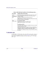
T1/E1 BITS LED
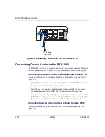
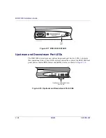
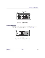
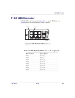
The BSR 2000 T1/E1 BITS interface has a green LED associated with it, located on
the rear panel to the right of the port, as shown in
. When lit, this LED
indicates that the BSR 2000 is locked to a reference clock from a T1- or E1-based
BITS source.
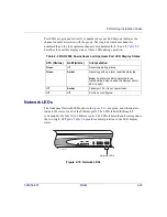
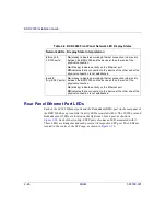
Table 2-5 BSR 2000 Rear Panel Ethernet Port LED Display States
Port LEDs
Display State Interpretation
10/100
(Ports 0 to 3 and
the Redundant
port)
On
(steady) indicates a working Ethernet connection (Link) exists
between the BSR 2000 and the device at the other end of the
physical connection.
On
(blinking) indicates activity on the Ethernet port.
Off
indicates that a connection to the device at the other end of the
physical connection is not established.
Gig-E
(Ports 4 and 5)
For copper-based SFPs:
On
indicates the presence of an SFP module.
Off
indicates the absence of an SFP module.
For fiber-based SFPs:
On
indicates that an SFP module is installed with a cable connected
to it, and that light is detected.
Off
indicates that light is not detected. This can be caused by the
absence of an SFP module, the absence of a cable connected to an
installed SFP module, or the absence of light when a cable is
connected to an installed SFP module (the Gig-E interface could be
shut down).

