Issue 1.1 April 2006
Page 117
10 Fault
Finding
If communication has been lost with the unit at the near end of the link then there may be a
hardware fault with the wiring, network or hardware. Go to the hardware section below. If
communication with the far end of the link is lost then go to the radio section below.
10.1 Hardware
If there are problems suspected with the link hardware the following procedure is
recommended.
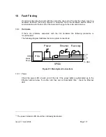
The following diagram illustrates the main system connections:
PSU
Power
Ethernet
Recovery
Mains
Power
To ODU
+55V
+55V
0V
0V
SPIDU
Figure 85: Main System Connections
10.1.1 Power
Check the power LED at each end of the link. If the power lights are illuminated go to the
Ethernet section below. If at either end they are not illuminated then
13
check the Ethernet
LED.
TP
13
PT
The power indicator LED should be continually illuminated.
Summary of Contents for Canopy 150 Mbps Backhaul
Page 1: ...Canopy 150 300 Mbps Backhaul User Guide BH150 300 UG en Issue 1 1 April 2006 ...
Page 25: ...Issue 1 1 April 2006 Page 24 Figure 5 Canopy 150 300 PIDU Power Input ...
Page 97: ...Issue 1 1 April 2006 Page 96 Figure 59 Spectrum Management Help Page ...
Page 162: ...Issue 1 1 April 2006 Page 161 Figure A8 Surge Arrestor ALPU ORT Connection Illustration ...


