Issue 1.1 April 2006
Page 84
Figure 46: Optional Post Disarm Configuration 1
After installation the system administrator may wish to modify the wireless unit’s descriptive
configuration (link name and link location). In addition the system administrator may wish to
change the spectrum management configuration of the wireless unit, or look at the analysis of
the 5.8 GHz spectrum to see if the automatic channel selection is appropriate for the system
administrator’s network. It is also recommended that a backup copy of the wireless unit’s
configuration is taken. Hyperlinks are provided on the post disarm page ( Figure 46) for ease
of use.
8.3.5 Graphical
Install
To aid the installation of wireless links two graphical installation aids have been introduced in
Canopy 150/300 Mb BH 58200.
•
A PDA installation screen
•
A larger installation screen available from the main HTTP management interface.
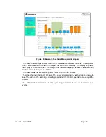
The design of the installation screen has been deliberately kept simple and uncluttered. An
example of the installation screen is shown in (Figure 46) Both the PDA and the large format
installation screen has the same content and only differs in size. The PDA installation screen
is 232 by 220 pixels to be compatible with the average size of a PDA screen.
Wireless Link Status.
Permissible values are: Up,
Registering, Searching and
Acquiring
Trace of receive power over
the previous three minutes
Receive Power Bar,
instantaneous receive
power. The colour of is
green when the wireless
link status is up,
otherwise it is red
Wireless Install
Metric
Figure 47: Installation Screen
The screen displays the receive power of the last three minutes. This will allow the installer to
slowly sweep the antenna during installation and monitor the variation in signal strength with
angular position. The screen automatically refreshes every three seconds.
The screen also displays the current state of the wireless link in two ways. Firstly the actual
state of the wireless link is written in the top left hand corner of the screen. The instantaneous
receive power bar also encodes the state of the wireless link using green to signify that the
wireless link is up and red for all other states.
Summary of Contents for Canopy 150 Mbps Backhaul
Page 1: ...Canopy 150 300 Mbps Backhaul User Guide BH150 300 UG en Issue 1 1 April 2006 ...
Page 25: ...Issue 1 1 April 2006 Page 24 Figure 5 Canopy 150 300 PIDU Power Input ...
Page 97: ...Issue 1 1 April 2006 Page 96 Figure 59 Spectrum Management Help Page ...
Page 162: ...Issue 1 1 April 2006 Page 161 Figure A8 Surge Arrestor ALPU ORT Connection Illustration ...

