Issue 1.1 April 2006
Page 85
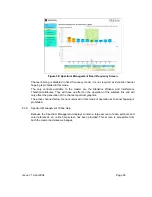
For the more technically aware the installation metric is simple the instantaneous receive
power in dBm + 50.
It is hoped that the installation screen will aid the small population of installers that find it
difficult to differentiate the small changes in tonal output when peaking up long range and or
marginal links.
The PDA installation tool is accessed via a hidden URL http://<ip-address>/pda.cgi. It should
be noted that this link is only available after the user has logged in as system administrator.
The large screen version of the graphical user interface is available as a submenu option of
the installation wizard.
8.3.6 Software
Upgrade
The Canopy 150/300 Mb BH system has two software image banks; one is a fixed image
which is stored in protected non-volatile memory and is not modifiable by the user, the
second bank is used by the system administrator to upgrade the firmware when necessary.
Figure 49 shows the main software upgrade webpage.
Figure 48: Software Upgrade
The ‘Fixed’ or ‘Recovery’ image is used by the System Administrator to:
•
Reset Ethernet configuration to default settings
•
Erase
Configuration
•
Upgrade
software
For a full description of the Recovery image see section 9 “Recovery Mode”.
The software upgrade pages are used to update a unit’s operational software. The software
image to be uploaded should be downloaded to local storage from
http://www.motorola.com/canopy
. The software image is delivered by Motorola as a
compressed zip file. Once the zip file has been downloaded the user should extract the
Canopy 150/300 Mb BH Software image, identifiable by its ‘.dld’ file extension.
The first step (Figure 48) is to use the “Browse” button to locate the software image
previously downloaded to local storage. Once the image is located the user should press the
“Upload image to wireless unit” button to start the software upgrade process.
Summary of Contents for Canopy 150 Mbps Backhaul
Page 1: ...Canopy 150 300 Mbps Backhaul User Guide BH150 300 UG en Issue 1 1 April 2006 ...
Page 25: ...Issue 1 1 April 2006 Page 24 Figure 5 Canopy 150 300 PIDU Power Input ...
Page 97: ...Issue 1 1 April 2006 Page 96 Figure 59 Spectrum Management Help Page ...
Page 162: ...Issue 1 1 April 2006 Page 161 Figure A8 Surge Arrestor ALPU ORT Connection Illustration ...

