Canopy
T1/E1
Multiplexer
September
2004
T1/E1
Multiplexer
FPGA
Version
3.4
Page
53 of 73
3
MANAGING
YOUR
CANOPY
T1/E1
MULTIPLEXERS
3.1
REMOTE
MANAGEMENT
THROUGH
CONTROL
PORT
The CONTROL port in the front panel (shown in
Figure 6
on Page
14
) provides the
capability to remotely manage the Canopy T1/E1 Multiplexer. To do so requires an
Ethernet to
RS-232 converter. An example of such a converter is available at
http://www.precidia.com/products/product1.html
.
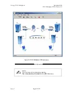
The configuration for remote management is illustrated in
Figure 20
.
Canopy T1/E1 Multiplexer
DB9
3.3-v
Wall
Mount
Supply
Canopy Ethernet
To
Ethernet
Network
To
E1/T1 Lines
Lightning/
Surge
Protector
Power
over
Ethernet
Canopy
ODU
48-v DC
Supply
Ethernet
Switch
Ethernet
to RS-232
Converter
Figure 20: Remote management overview
Issue
3

