MOTOROLA CMOS LOGIC DATA
MC14549B MC14559B
6–404
Q7 Q6 Q5
MR
SC
C
Sout
MC14549B
Q4 Q3 Q2 Q1 Q0 EOC
Sout
TO DAC
Q7 Q6 Q5
SC
C
Sout
MC14559B
Q4 Q3 Q2 Q1 Q0
EOC
TO DAC
FF
EOC
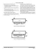
Figure 4. Continuously Cycling 12–Bit ADC
the 12–bit conversion cycle, the end of the serial output
word, and the validity of the parallel data output.
Externally Controlled 12–Bit ADC (Figure 5)
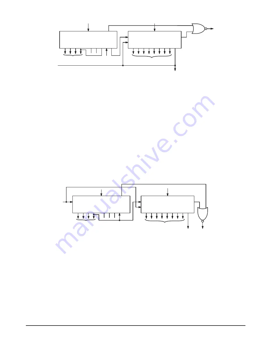
In this circuit the external pulse starts the first SAR and
simultaneously resets the cascaded second SAR. When Q4
of the first SAR goes high, the second SAR starts conver-
sion, and the first one stops conversion. EOC indicates that
the parallel data are valid and that the serial output is com-
plete. Updating the output data is started with every external
control pulse.
Additional Motorola Parts for Successive
Approximation ADC
Monolithic digital–to–analog converters — The
MC1408/1508 converter has eight–bit resolution and is avail-
able with 6, 7, and 8–bit accuracy. The amplifier–compara-
tor block — The MC1407/1507 contains a high speed
operational amplifier and a high speed comparator with ad-
justable window.
With these two linear parts it is possible to construct SA–
ADCs with an accuracy of up to eight bits, using as the regis-
ter one MC14549B or one MC14559B. An additional CMOS
block will be necessary to generate the clock frequency.
Additional information on successive approximation ADC
is found in Motorola Application Note AN–716.
Figure 5. Externally Controlled 12–Bit ADC
Q7 Q6 Q5
MR
SC
C
Sout
MC14549B
Q4 Q3 Q2 Q1 Q0 EOC
Sout
TO DAC
Q7 Q6 Q5
SC
C
Sout
MC14559B
Q4 Q3 Q2 Q1 Q0
EOC
TO DAC
FF
EOC
Summary of Contents for CMOS Logic
Page 1: ......
Page 5: ...iv MOTOROLA CMOS LOGIC DATA ...
Page 6: ...Master Index 1 ...
Page 12: ...Product Selection Guide 2 ...
Page 17: ...The Better Program 3 ...
Page 20: ...B and UB Series Family Data 4 ...
Page 25: ...CMOS Handling and Design Guidelines 5 ...
Page 32: ...CMOS Handling and Design Guidelines 5 ...
Page 39: ...Data Sheets 6 ...
Page 234: ...MOTOROLA CMOS LOGIC DATA MC14174B 6 196 FUNCTIONAL BLOCK DIAGRAM TIMING DIAGRAM ...
Page 238: ...MOTOROLA CMOS LOGIC DATA MC14175B 6 200 FUNCTIONAL BLOCK DIAGRAM TIMING DIAGRAM ...
Page 555: ...CMOS Reliability 7 ...
Page 561: ...Equivalent Gate Count 8 ...
Page 563: ...Packaging Information Including Surface Mounts 9 ...
Page 571: ......


