Memory Module Installation
http://www.motorola.com/computer/literature
1-9
1
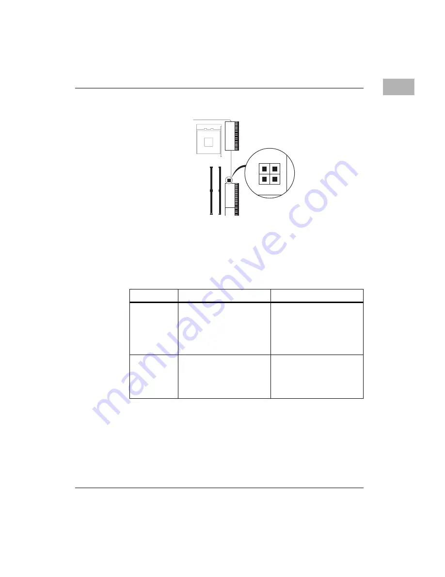
Jumpering Diagram for Header E1
Note
The USB port on the front panel of the SBC is used for
maintenance only. For data transfer in an end application, USB
ports are available via the RTM.
Apply the jumpers according to the following table.
Memory Module Installation
The CPIP5430 depends upon a proprietary memory module and
specialized signal routing to obtain densities of 2GB per SODIMM socket.
All standard DDR SODIMM modules are compatible, however, 2GB is
only achievable with the purchase of a special memory module.
Jumper
Function
Setting
E4
Reserved
Routes Ethernet signal to the
RTM
Routes Ethernet signal to the
CPIP5430 front panel
[1-2] jumper off
[3-4] jumper on
[3-4] jumper off
E1
Default
Standalone operation
+12V power to RTM for
USB control
{1-2, 3-4] no jumper
[1-2] jumper on
[3-4] jumper on
4278 0504
J5
J3
J11
J7
J10
J6
2
1
4
3
E1


