CPU12
ADDRESSING MODES
MOTOROLA
REFERENCE MANUAL
3-7
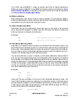
3.8.2 9-Bit Constant Offset Indexed Addressing
This indexed addressing mode uses a 9-bit signed offset which is added to the base
index register (X, Y, SP, or PC) to form the effective address of the memory location
affected by the instruction. This gives a range of
–
256 t255 from the value in
the base index register. The most significant bit (sign bit) of the offset is included in the
instruction postbyte and the remaining eight bits are provided as an extension byte af-
ter the instruction postbyte in the instruction flow.
Examples:
LDAA
$FF,X
LDAB
–
20,Y
For these examples assume X is $1000 and Y is $2000 before execution of these in-
structions. (These instructions do not alter the index registers so they will still be $1000
and $2000 respectively after the instructions.) The first instruction will load A with the
value from address $10FF and the second instruction will load B with the value from
address $1FEC.
This variation of the indexed addressing mode in the CPU12 is similar to the M68HC11
indexed addressing mode, but is functionally enhanced. The M68HC11 CPU provides
for unsigned 8-bit constant offset indexing from X or Y, and use of Y requires an extra
instruction byte and thus, an extra execution cycle. The 9-bit signed offset used in the
CPU12 covers the same range of positive offsets as the M68HC11, and adds negative
offset capability. The CPU12 can use X, Y, SP or PC as the base index register.
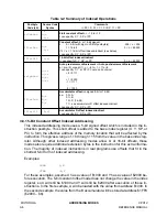
3.8.3 16-Bit Constant Offset Indexed Addressing
This indexed addressing mode uses a 16-bit offset which is added to the base index
register (X, Y, SP, or PC) to form the effective address of the memory location affected
by the instruction. This allows access to any address in the 64-Kbyte address space.
Since the address bus and the offset are both 16 bits, it does not matter whether the
offset value is considered to be a signed or an unsigned value ($FFFF may be thought
of as +65,535 or as
–
1). The 16-bit offset is provided as two extension bytes after the
instruction postbyte in the instruction flow.
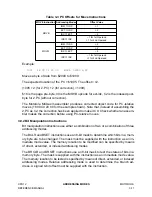
3.8.4 16-Bit Constant Indirect Indexed Addressing
This indexed addressing mode adds a 16-bit instruction-supplied offset to the base in-
dex register to form the address of a memory location that contains a pointer to the
memory location affected by the instruction. The instruction itself does not point to the
address of the memory location to be acted upon, but rather to the location of a pointer
to the address to be acted on. The square brackets distinguish this addressing mode
from 16-bit constant offset indexing.
Example:
LDAA
[10,X]
Summary of Contents for CPU12
Page 8: ...MOTOROLA CPU12 viii REFERENCE MANUAL ...
Page 14: ...MOTOROLA INTRODUCTION CPU12 1 4 REFERENCE MANUAL ...
Page 20: ...MOTOROLA OVERVIEW CPU12 2 6 REFERENCE MANUAL ...
Page 38: ...MOTOROLA INSTRUCTION QUEUE CPU12 4 6 REFERENCE MANUAL ...
Page 300: ...MOTOROLA DEVELOPMENT AND DEBUG SUPPORT CPU12 8 16 REFERENCE MANUAL ...
Page 338: ...MOTOROLA MEMORY EXPANSION CPU12 10 8 REFERENCE MANUAL ...
Page 364: ...MOTOROLA INSTRUCTION REFERENCE CPU12 A 26 REFERENCE MANUAL ...
Page 386: ...MOTOROLA HIGH LEVEL LANGUAGE SUPPORT CPU12 C 6 REFERENCE MANUAL ...
Page 438: ...MOTOROLA SUMMARY OF CHANGES CPU12 S 2 REFERENCE MANUAL ...
Page 439: ......


