CPU12
FUZZY LOGIC SUPPORT
MOTOROLA
REFERENCE MANUAL
9-15
The instruction LDAA #$FF clears the V bit at the same time it initializes A to $FF. This
satisfies the REV setup requirement to clear the V bit as well as the requirement to
initialize A to $FF. Once the REV instruction starts, the value in the V bit is automati-
cally maintained as $FE separator characters are detected.
The final requirement to clear all fuzzy outputs to $00 is part of the MAX algorithm.
Each time a rule consequent references a fuzzy output, that fuzzy output is compared
to the truth value for the current rule. If the current truth value is larger, it is written over
the previous value in the fuzzy output. After all rules have been evaluated, the fuzzy
output contains the truth value for the most-true rule that referenced that fuzzy output.
After REV finishes, A will hold the truth value for the last rule in the rule list. The V con-
dition code bit should be one because the last element before the $FF end marker
should have been a rule consequent. If V is zero after executing REV, it indicates the
rule list was structured incorrectly.
9.5.1.2 Interrupt Details
The REV instruction includes a three-cycle processing loop for each byte in the rule
list (including antecedents, consequents, and special separator characters). Within
this loop, a check is performed to see if any qualified interrupt request is pending. If an
interrupt is detected, the current CPU registers are stacked and the interrupt is hon-
ored. When the interrupt service routine finishes, an RTI instruction causes the CPU
to recover its previous context from the stack, and the REV instruction is resumed as
if it had not been interrupted.
The stacked value of the program counter (PC), in case of an interrupted REV instruc-
tion, points to the REV instruction rather than the instruction that follows. This causes
the CPU to try to execute a new REV instruction upon return from the interrupt. Since
the CPU registers (including the V bit in the condition codes register) indicate the cur-
rent status of the interrupted REV instruction, this effectively causes the rule evalua-
tion operation to resume from where it left off.
9.5.1.3 Cycle-by-Cycle Details for REV
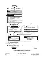
The central element of the REV instruction is a three-cycle loop that is executed once
for each byte in the rule list. There is a small amount of housekeeping activity to get
this loop started as REV begins, and a small sequence to end the instruction. If an in-
terrupt comes, there is a special small sequence to save CPU status on the stack be-
fore honoring the requested interrupt.
is a REV instruction flow diagram. Each rectangular box represents one
CPU clock cycle. Decision blocks and connecting arrows are considered to take no
time at all. The letters in the small rectangles in the upper left corner of each bold box
correspond to execution cycle codes (refer to
for details). Lower case letters indicate a cycle where 8-bit or no data is transferred.
Upper case letters indicate cycles where 16-bit or no data is transferred.
Summary of Contents for CPU12
Page 8: ...MOTOROLA CPU12 viii REFERENCE MANUAL ...
Page 14: ...MOTOROLA INTRODUCTION CPU12 1 4 REFERENCE MANUAL ...
Page 20: ...MOTOROLA OVERVIEW CPU12 2 6 REFERENCE MANUAL ...
Page 38: ...MOTOROLA INSTRUCTION QUEUE CPU12 4 6 REFERENCE MANUAL ...
Page 300: ...MOTOROLA DEVELOPMENT AND DEBUG SUPPORT CPU12 8 16 REFERENCE MANUAL ...
Page 338: ...MOTOROLA MEMORY EXPANSION CPU12 10 8 REFERENCE MANUAL ...
Page 364: ...MOTOROLA INSTRUCTION REFERENCE CPU12 A 26 REFERENCE MANUAL ...
Page 386: ...MOTOROLA HIGH LEVEL LANGUAGE SUPPORT CPU12 C 6 REFERENCE MANUAL ...
Page 438: ...MOTOROLA SUMMARY OF CHANGES CPU12 S 2 REFERENCE MANUAL ...
Page 439: ......


