MOTOROLA
M68HC11 TO M68HC12 UPGRADE PATH
CPU12
B-8
REFERENCE MANUAL
B.5.2 Auto-Increment Indexing
The CPU12 provides greatly enhanced auto increment and decrement modes of in-
dexed addressing. In the CPU12, the index modification may be specified for before
the index is used (pre-), or after the index is used (post-), and the index can be incre-
mented or decremented by any amount from one to eight, independent of the size of
the operand that was accessed. X, Y, and SP can be used as the index reference, but
this mode does not allow PC to be the index reference (this would interfere with prop-
er program execution).
This addressing mode can be used to implement a software stack structure, or to ma-
nipulate data structures in lists or tables, rather than manipulating bytes or words of
data. Anywhere an M68HC11 program has an increment or decrement index register
operation near an indexed mode instruction, the increment or decrement operation
can be combined with the indexed instruction with no cost in object code size, as
shown in the following code comparison.
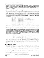
The M68HC11 object code requires seven bytes, while the CPU12 requires only two
bytes to accomplish the same functions. Three bytes of M68HC11 code were due to
the page prebyte for each Y-related instruction ($18). CPU12 post-increment indexing
capability allowed the two INY instructions to be absorbed into the LDAA indexed
instruction. The replacement code is not identical to the original three instruction se-
quence because the Z condition code bit is affected by the M68HC11 INY instruc-
tions, while the Z bit in the CPU12 would be determined by the value loaded into A.
B.5.3 Accumulator Offset Indexing
This indexed addressing variation allows the programmer to use either an 8-bit accu-
mulator (A or B), or the 16-bit D accumulator as the offset for indexed addressing.
This allows for a program-generated offset, which is more difficult to achieve in the
M68HC11. The following code compares the M68HC11 and CPU12 operations.
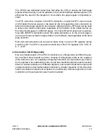
The CPU12 object code is only one byte smaller, but the LDX # instruction is outside
the loop. It is not necessary to reload the base address in the index register on each
pass through the loop because the LDAA B,X instruction does not alter the index
register. This reduces the loop execution time from 15 cycles to six cycles. This re-
duction, combined with the 8-MHz bus speed of the M68HC12 family, can have signif-
icant effects.
18 A6 00
18 08
18 08
LDAA
0,Y
INY
INY
A6 71
LDAA
2,Y+
C6 05
CE 10 00
3A
A6 00
5A
26 F7
LDAB
#$5
[2]
LOOP
LDX
#$1000
[3]
ABX
[3]
LDAA
0,X
[4]
|
DECB
[2]
BNE
LOOP
[3]
C6 05
CE 10 00
A6 E5
04 31 FB
LDAB
#$5
[1]
LDX
#$1000
[2]
LOOP
LDAA
B,X
[3]
|
DBNE
B,LOOP
[3]
Summary of Contents for CPU12
Page 8: ...MOTOROLA CPU12 viii REFERENCE MANUAL ...
Page 14: ...MOTOROLA INTRODUCTION CPU12 1 4 REFERENCE MANUAL ...
Page 20: ...MOTOROLA OVERVIEW CPU12 2 6 REFERENCE MANUAL ...
Page 38: ...MOTOROLA INSTRUCTION QUEUE CPU12 4 6 REFERENCE MANUAL ...
Page 300: ...MOTOROLA DEVELOPMENT AND DEBUG SUPPORT CPU12 8 16 REFERENCE MANUAL ...
Page 338: ...MOTOROLA MEMORY EXPANSION CPU12 10 8 REFERENCE MANUAL ...
Page 364: ...MOTOROLA INSTRUCTION REFERENCE CPU12 A 26 REFERENCE MANUAL ...
Page 386: ...MOTOROLA HIGH LEVEL LANGUAGE SUPPORT CPU12 C 6 REFERENCE MANUAL ...
Page 438: ...MOTOROLA SUMMARY OF CHANGES CPU12 S 2 REFERENCE MANUAL ...
Page 439: ......

