I n s t a l l a t i o n
3333 ---- 5555
D C T 2 0 0 0 I n s t a l l a t i o n M a n u a l
R F B y p a s s S w i t c h V C R C a b l i n g D i a g r a m s
Proper operation of the RF Bypass feature requires special configuration in the control system
and in the EPG settings.
The STARFONE return module is used in a one-way addressable system to send information to
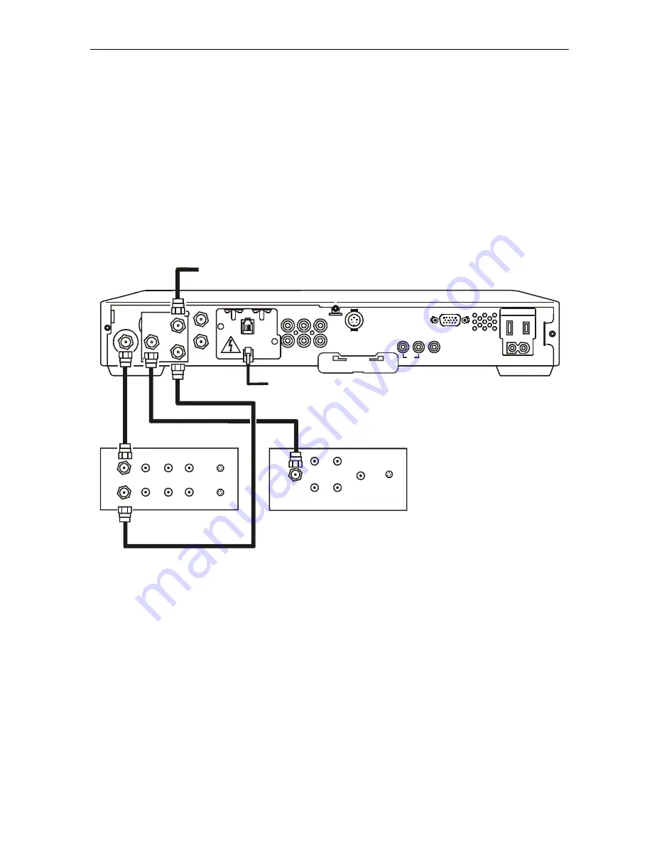
the controller through the subscriber’s telephone hookup. Figure 3-4 illustrates the cabling
diagram that enables viewing an unscrambled analog channel on TV while recording another
channel through the DCT 2000:
F i g u r e 3 - 4
R F B y p a s s s w i t c h w i t h V C R ( S T A R F O N E r e t u r n m o d u l e i n s t a l l e d )
TV
CABLE IN
VIDEO
IN
SVIDEO
IN
AUDIO
IN
L
R
AUDIO
OUT
L
R
VCR
CABLE IN
VIDEO IN
AUDIO
IN
L
R
CABLE OUT
VIDEO OUT
AUDIO
OUT
L
R
SVIDEO IN
SVIDEO OUT
RF
IN
CAB LE IN
TO RF IN
T V Pass Card
S-V IDEO
BAND
IR
SPEED
HIGH
OUT OF
SWITCHED
60Hz
500W MAX
105-125V
4A MAX
TO
T V/VCR
DATA
R
AUX AUD IO IN
SPDIF
AUD IO OU T
V IDEO
L
From cable source
Subscriber telephone hookup
PHONE
RF
OUT
RF
IN
CONV
IN
If the operator plans to implement two-way RF return functionality in the future, the installer
should use the integrated STARVUE RF return.
Summary of Contents for DCT2000
Page 70: ...02 00 469714 001 99 ...


