Installation 3-9
DCT2500 Installation Manual
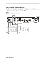
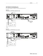
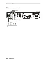
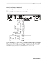
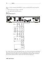
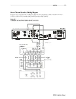
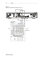
Stereo Cabling Diagram (Baseband)
This audio configuration does not provide for a TV playing through the stereo:
Figure 3-9
Connecting the DCT2500 to a stereo using the audio connectors on the VCR
L
R
AUDIO
OUT
AUDIO
IN
AUDIO
OUT
TO
RF IN
TO
TV/VCR
RF IN
CABLE
IN
DIGITAL
AUDIO
OPTICAL
DIGITAL
AUDIO
COAX
VIDEO
DATA
USB
IR
PHONE
TV PASS CARD
SWITCHED
105-125V
60Hz
4A MAX
500W MAX
S-VIDEO
R
TO TV
TO VCR
L
DCT2500
CABLE IN
VIDEO IN
AUDIO
IN
L
R
CABLE OUT
VIDEO OUT
AUDIO
OUT L
R
S-VIDEO IN
S-VIDEO OUT
Either / or
CABLE IN
VIDEO
IN
S-VIDEO
IN
AUDIO
IN
L
R
AUDIO
OUT
L
R
Either / or
VCR
TV
STEREO
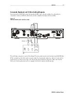
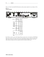
The S-Video connector is part of the Home Theatre option and is not included on all DCT2500s.
When connecting the video path, connect either the baseband composite video or S-video to the
input device you plan to use. Do not connect both the baseband composite video and S-video.
Some electronic equipment will not support both video inputs simultaneously.

