


Summary of Contents for DCT3412
Page 1: ......
Page 26: ...3 10 Installation Figure 3 4 Connecting a Stereo TV DCT3412 Installation Manual ...
Page 77: ......
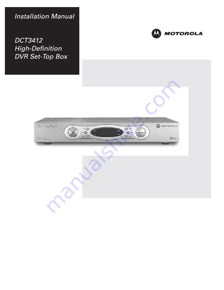
The Motorola DCT3412 is a feature-rich set-top box that brings seamless entertainment to your TV. With its user-friendly interface and high-definition capabilities, this device offers unmatched viewing experience. Need help setting it up? Download the free Installation Manual from 88.208.23.73:8080 to unleash the full potential of your Motorola DCT3412.
Page 1: ......
Page 26: ...3 10 Installation Figure 3 4 Connecting a Stereo TV DCT3412 Installation Manual ...
Page 77: ......


