background image


4


RF IN 2

L

L

AUDIO

IN

AUDIO

OUT

R

R

OPTICAL

SPDIF

S-VIDEO

IR

RF IN 1

RPT OUT

CM IN

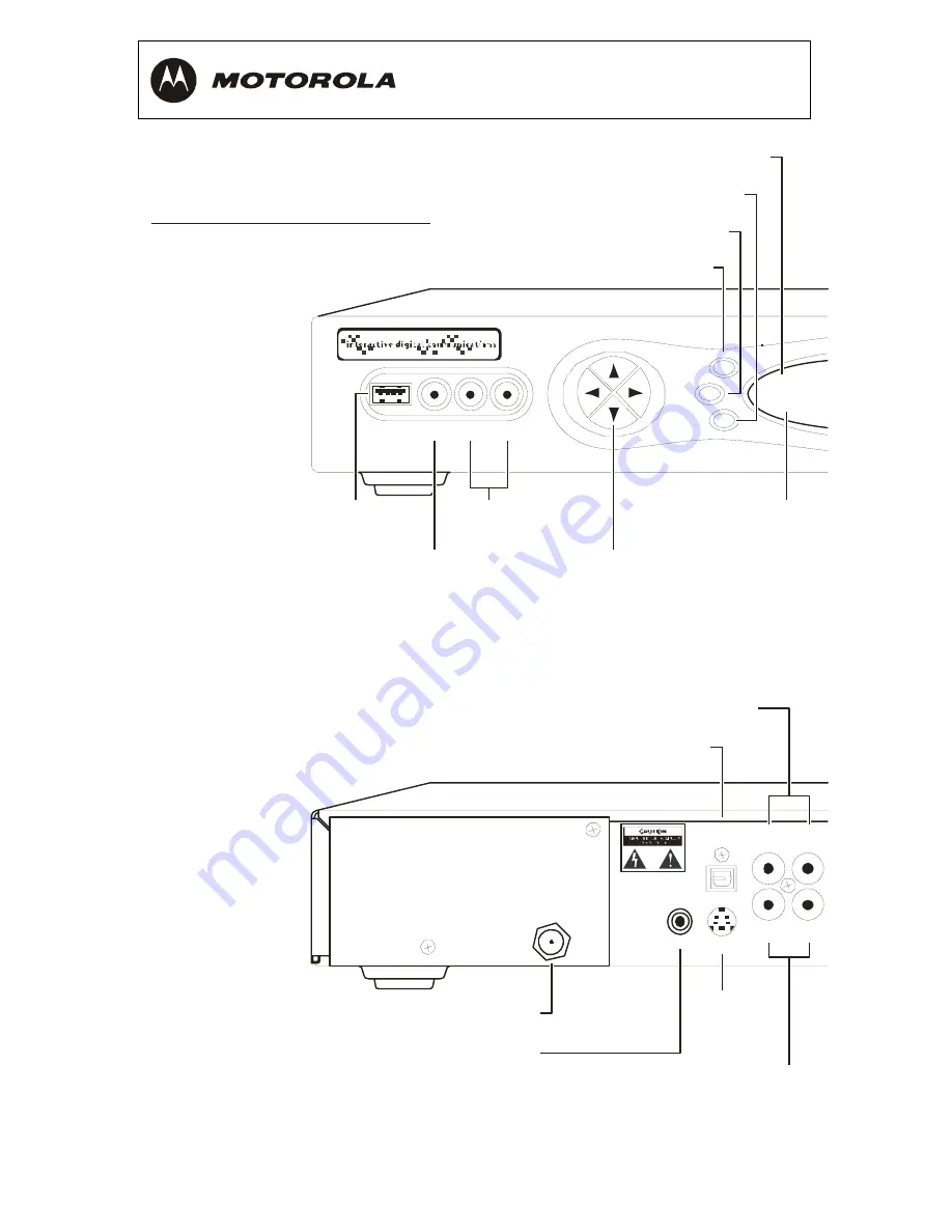
FRONT PANEL

AUDIO IN (L/R)*

POWER switch

INFO switch

MENU switch

AUDIO OUT (R/L)

Audio output to stereo receiver

Audio input from

CD player or tuner

Turns unit on or off

Displays current channel and program information

Displays menu

VIDEO IN*

Video input from VCR,

camcorder, or other device

USB 2.0

Connector

CABLE IN 

Input from cable provider 

IR

Enables you to control VCR

while recording selected program

(Not supported by all program guides)

INFO

M ENU

PO WER

CURSO R

M SG S.

O N

USB 2 .0

VIDEO  IN

L   AUDIO  IN   R

CURSOR

Moves cursor around guide

and menu screens

POWER indicator

Lights when

unit is on

Message Indicator

Lights when message is waiting

AUDIO IN (R/L)*

OPTICAL SPDIF

Audio input from CD player or tuner

Dua l Tu ne r  DVR  /  HDTV Ca pa ble

Provides Dolby  Digital 5.1 audio or PCM audio

®

S-VIDEO

Output to

TV or VCR

CABLE

IN

Summary of Contents for DCT6400 Phase III

Page 1: ...User Guide DCT6400 High Definition DVR Cable Terminal Phase III ...

Page 2: ... a risk of electric shock to persons The exclamation point within an equilateral triangle is intended to alert the user to the presence of important operating and maintenance servicing instructions in the literature accompanying the appliance REPAIRS If you find the unit in need of repair call Motorola Support at 1 866 668 2271 or 1 866 MOT BCS1 NOTE TO CATV SYSTEM INSTALLER This reminder is provi...

Page 3: ...g prong The wide blade or the third prong are provided for your safety If the provided plug does not fit into your outlet consult an electrician for replacement of the obsolete outlet 10 Protect the power cord from being walked on or pinched particularly at plugs convenience receptacles and the point where they exit from the apparatus 11 Only use attachments accessories specified by the manufactur...

Page 4: ...he party responsible for compliance could void the user s authority to operate the equipment Declaration of Conformity According to 47 CFR Parts 2 and 15 for Class B Personal Computers and Peripherals and or CPU Boards and Power Supplies used with Class B Personal Computers Motorola Inc 6450 Sequence Drive San Diego CA 92121 1 800 225 9446 declares under sole responsibility that the product identi...

Page 5: ...oftware to make it operate on non compatible hardware 4 Remove alter or cause not to be displayed any copyright notices or startup message contained in the Software programs or documentation 5 Export the Software or the Product components in violation of any United States export laws The Product is not designed or intended for use in on line control of aircraft air traffic aircraft navigation or a...

Page 6: ...itten permission from Motorola Inc Motorola reserves the right to revise this publication and to make changes in content from time to time without obligation on the part of Motorola to provide notification of such revision or change Motorola provides this guide without warranty of any kind either implied or expressed including but not limited to the implied warranties of merchantability and fitnes...

Page 7: ... Considerations 15 Connecting Your DCT6400 to aN HDTV Video Only 16 Connecting HDTV Video Only 17 Connecting Your DCT6400 to a HDTV Audio Only 18 Connecting HDTV Audio Only 19 Connecting Your DCT6400 to an A V Receiver Audio Only 20 Connecting an A V Receiver Audio Only 21 Connecting Your DCT6400 to a Stereo TV 22 Connecting a Stereo TV 23 Connecting Your DCT6400 to a Stereo TV and Stereo VCR 24 C...

Page 8: ...2 Recording Your Connections 28 Data Devices 29 Troubleshooting 30 ...

Page 9: ...h and record functionality This User Guide introduces the basic features outlines important safeguards and provides options for integrating your DCT6400 into your entertainment system Please take a few moments to read through this User Guide The configuration diagrams on screen menu description and troubleshooting section will help you make the most of your home entertainment experience To determi...

Page 10: ...er or other device USB 2 0 Connector CABLE IN Input from cable provider IR Enables you to control VCR while recording selected program Not supported by all program guides INFO M ENU PO WER CUR SO R M SG S O N USB2 0 VIDEO IN L AUDIO IN R CURSOR Moves cursor around guide and menu screens POWER indicator Lights when unit is on Message Indicator Lights when message is waiting AUDIO IN R L OPTICAL SPD...

Page 11: ... TV VCR or other device Y Pb Pr HDTV video output USB 2 0 Connector SATA Connects to external hard drive IEEE 1394 HDTV output O PTIO N G UIDE SELECT CHANNEL SM AR TCAR D R EM OTE R ECO R D DCT 6400 III RECORD Indicator SELECT switch OPTION switch GUIDE switch Lights when DVR is recording Selects menu options Reserved Displays program guide SMART CARD CHANNEL Supports Smart Card functionality Scro...

Page 12: ...ng the Volume Press VOLUME or on the remote control to adjust the volume When you adjust the volume the volume scale is displayed on the screen Press MUTE on the remote control to turn the sound off and on again For best audio quality use the remote control to set the DCT6400 to approximately of the maximum volume level and then adjust the audio levels on external devices such as your TV or A V Re...

Page 13: ...depends on your hard drive capacity and content type digital analog or HD that you record Maintain a Personal Program Library Maintain a personal library of recorded programming accessed using the interactive program guide IPG Control Live TV Pause rewind or fast forward live TV Simultaneously Watch Two Programs Watch two programs and easily switch between them using the SWAP key on your remote co...

Page 14: ...ss than 20 meters long You can configure the TV type HDMI and or Y Pb Pr video output and closed captioning To optimize the output settings 1 Be sure your DCT6400 is plugged into a power outlet and connected to your TV 2 Power off the DCT6400 and then immediately press the MENU key on the front panel If your TV is on the on screen menu lists the settings you can configure USER SETTINGS TV TYPE 16 ...

Page 15: ...scription TV Type Sets the aspect ratio The front panel display indicates the type you select Defaults to 16 9 Options are 16 9 for wide screen TVs or 4 3 LETTERBOX or 4 3 PAN SCAN for standard TVs 4 3 LETTERBOX fits widescreen programming on the screen by placing black bars at the top and bottom 4 3 PAN SCAN fills the screen by cropping the left and right edges of widescreen programming HDMI YPbP...

Page 16: ...their component video inputs YPbPr Check the TV user manual for more information Stretch automatically stretches all standard definition programming to fill your widescreen display Stretch can only be selected if you have TV Type set to 16 9 Closed Caption Turns closed captions off or on The front panel display indicates the status of the closed captions Defaults to DISABLED Options are ENABLED or...

Page 17: ...TO TRANSPARENT TRANSLUCENT SOLID or FLASHING Settings Sets the default settings for closed captions AUTO or the settings you have configured USER Defaults to AUTO Options are AUTO or USER Restore All Defaults To reset all User Settings to their defaults select this option and press the key For HDMI only when you first connect a TV to the DCT6400 using the HDMI connection the TV and the DCT6400 exc...

Page 18: ...on screen Common examples include on screen menus such as the User Setting menu closed captions and interactive program guides The DCT6400 overlays these graphics whenever you display a menu enable closed captions or scroll through a program grid On screen graphics are available for all DCT6400 video outputs except for IEEE 1394 ...

Page 19: ... Before you move or change components on your entertainment system review the following For basic cable connections use 75 ohm coaxial cables equipped with F type connectors Disconnect power from the cable terminal before connecting or changing cable connections For information on connecting for HDTV see Video Options on the next page CAUTION Do not place anything on top of the cable terminal espe...

Page 20: ...fer higher video quality than component video If your TV has an HDMI input use the HDMI connections on your DCT6400 instead of IEEE 1394 Motorola recommends using HDMI cables less than 20 meters long HDMI and IEEE 1394 are video and audio connections If you use HDMI or IEEE 1394 no separate audio connection to your TV is required HDMI is compatible with DVi If your TV has a DVI input you can use a...

Page 21: ...with at least 2 inches of space above and on all sides Do not block the slots and openings Do not place anything on top of the DCT6400 Do not position the DCT6400 in an enclosed space that would restrict airflow around the unit Do not position the DCT6400 near any external heat source that could raise the temperature around the unit Do not place the terminal on top of another heat producing electr...

Page 22: ...OUT RFIN 1 RPTOUT CM IN CABLE IN SWITCHED 105 125V 60Hz 4AMAX 500W MAX IEEE 1394 TV PASS CARD SATA USB ETHERNET HDMI Pr OUT VIDEO Pb Y IN SPDIF CABLE ANTENNA IN Component Video Input Y Pb Pr HDM I IEEE 1394 IEEE 1394 connection HDMI connection HDTV Component video connection Either or Cable in DCT6400 Phase III ...

Page 23: ...has a HDMI input connect an HDMI cable less than 20 meters long to the HDMI OUT connector on your HDTV and the DCT6400 If you use the TV as the primary audio source or your home theater receiver has an HDMI input and output the HDMI connection carries video and audio If your TV has a DVI input you can use an HDMI to DVI converter cable to connect to the DCT6400 HDMI connector For information on co...

Page 24: ...X AUDIO RIGHT RFIN 2 L L AUDIO IN AUDIO OUT R R OPTICAL SPDIF S VIDEO IR RFOUT RFIN 1 RPTOUT CM IN CABLE IN SWITCHED 105 125V 60Hz 4AMAX 500W MAX IEEE 1394 TV PASS CARD SATA USB ETHERNET HDMI Pr OUT VIDEO Pb Y IN SPDIF Cable in DCT6400 Phase III Audio connection Optical SPDIF connection Either or SPDIF audio connection ...

Page 25: ...DIF or coaxial digital SPDIF outputs instead of the AUDIO R and L outputs In most cases S PDIF offers better audio quality including support for Dolby 5 1 Surround Sound HDMI and IEEE1394 carry video and audio If you connect the DCT6400 to your HDTV using HDMI or IEEE1394 no additional audio connections to the TV are necessary For information on configuring your DCT6400 settings see Optimizing You...

Page 26: ...ITCHED 105 125V 60Hz 4AMAX 500W MAX IEEE 1394 TV PASS CARD SATA USB ETHERNET HDMI Pr OUT VIDEO Pb Y IN SPDIF DCT6400 Phase III A V receiver DIGITAL INPUT TV M ONITOR OUTPUT SPEAKER CONNECTORS COAX VIDEO S VIDEO R DVD CABLE TV VIDEO 2 IN OUT VCR AUDIO VIDEO L VIDEO S VIDEO OPTICAL Audio connection Optical SPDIF connection SPDIF audio connection Either or ...

Page 27: ...or on the DCT6400 and the corresponding connector on the A V receiver Stereo audio R and L Connect the stereo audio cable to the AUDIO R and L connectors on the DCT6400 and the corresponding connectors on the A V receiver If you re A V receiver supports it use the OPTICAL SPDIF or coaxial SPDIF outputs on the DCT6400 instead of its stereo AUDIO R and L outputs In most cases S PDIF offers better au...

Page 28: ...RNET HDMI Pr OUT VIDEO Pb Y IN SPDIF DCT6400 Phase III CABLE ANTENNA IN INPUT S VIDEO VIDEO AUDIO LEFT AUDIO RIGHT Stereo TV Either or RF 75 ohm connection Video connection S Video connection Audio connection Cable in Depending on the TV s inputs 1 If possible use the S VIDEO and AUDIO connectors on the DCT6400 2 If the TV has no S Video input use the composite VIDEO and AUDIO connectors on the DC...

Page 29: ...DIO R and L connectors on the DCT6400 and the corresponding connectors on the stereo TV 3 Connect an S video cable to the S VIDEO connectors on the DCT6400 and the TV or Connect a video cable to the VIDEO OUT connector on the DCT6400 and the VIDEO IN connector on the TV This video connection method does not support HD video For more information see Connecting Your DCT6400 to an HDTV Video Only ...

Page 30: ...IN SWITCHED 105 125V 60Hz 4AMAX 500W MAX IEEE 1394 TV PASS CARD SATA USB ETHERNET HDMI Pr OUT VIDEO Pb Y IN SPDIF To TV CABL E ANTENNA IN INPUT AUDIO L R VIDEO OUT PUT AUDIO L R VIDEO CABLE ANTENNA IN INPUT S VIDEO VIDEO AUDIO LEFT AUDIO RIGHT Stereo TV Stereo VCR RF 75 ohm connection Video connection Audio connection Cable in DCT6400 Phase III ...

Page 31: ... Connect a video cable to the VIDEO OUT connector on the DCT6400 and the INPUT VIDEO connector on the stereo VCR 4 Connect a stereo audio cable to the OUTPUT AUDIO R and L connectors on the stereo VCR and the INPUT AUDIO RIGHT and LEFT connectors on the stereo TV 5 Connect a video cable to the OUTPUT VIDEO connector on the stereo VCR and the INPUT VIDEO connector on the stereo TV This video connec...

Page 32: ...OUT VIDEO Pb Y IN SPDIF Cable in DIGITAL INPUT TV M ONITOR OUTPUT SPEAKER CONNECTORS COAX VIDEO S VIDEO R DVD CABLE TV VIDEO 2 IN OUT VCR AUDIO VIDEO L VIDEO S VIDEO OPTICAL CABLE ANTENNA IN INPUT S VIDEO VIDEO AUDIO LEFT AUDIO RIGHT To TV CABLE ANTENNA IN INPUT AUDIO L R VIDEO OUTPUT AUDIO L R VIDEO Stereo VCR A V receiver Stereo TV RF 75 ohm connection Video connection Audio connection Optical S...

Page 33: ... AUDIO IN R and L connectors on the A V receiver 6 Connect a video cable to the INPUT VIDEO connector on the stereo VCR and the VIDEO VCR OUT connector on the A V receiver 7 Connect a video cable to the OUTPUT VIDEO connector on the stereo VCR and the VIDEO VCR IN connector on the A V receiver 8 Connect a video cable to the INPUT VIDEO connector on the stereo TV and the TV MONITOR OUTPUT video con...

Page 34: ...IN INPUT AUDIO L R VIDEO OUT PUT AUDIO L R VIDEO DCT6400 Phase III VCR DIGITAL INPUT TV M ONIT OR OUTPUT SPEAKER CONNECTORS COAX VIDEO S VIDEO R DVD CABL E TV VIDEO 2 IN OUT VCR AUDIO VIDEO L VIDEO S VIDEO OPT ICAL A V receiver DVD IN OUT TAPE 1 R CD IN AUX IN L SPEAKER CONNECTORS Stereo receiver TV CABL E ANT ENNA IN L R S VIDEO IN HDM I S VIDEO OUT VIDEO IN AUDIO IN AUDIO OUT VIDEO OUT L M ONO R...

Page 35: ...ices External hard drive USB devices Do not attempt to connect data devices without contacting your service provider Advanced data features require the proper application and network infrastructure to operate In addition to high quality audio and video the DCT6400 can deliver high speed data services such as Internet access e mail IP Telephony E Commerce and home banking The functionality of the i...

Page 36: ...d to a switched outlet on another unit verify that that unit is powered on Press the POWER button on the DCT6400 front panel instead of the remote control The batteries in the remote control may be depleted The remote control does not work Verify that the remote control is in Cable mode Verify that there are no obstructions between the remote control and the DCT6400 Aim the remote control directly...

Page 37: ... used the correct audio cables for the ports Verify that the audio cables are firmly connected between the DCT6400 and the audio playback device TV receiver DVD player etc There is no audio from the center and or surround speakers of a home theater receiver connected to the DCT6400 Not all Dolby Digital programs feature full 5 1 surround sound In some cases the programs may only contain left and r...

Page 38: ...and then power on the devices Not all HDTVs can display every output format 1080i 720p 480p or 480i available on the DCT6400 To select a different format 1 Ensure that your DCT6400 is plugged into a power outlet and is turned off 2 Press the MENU key on the front panel Your settings are displayed on the DCT6400 front panel display 3 Press the and keys to display the HDMI YPbPr OUTPUT setting 4 Pre...

Page 39: ...hese programs are broadcast in 16 9 HD formats even though the video is not 16 9 There are black bars above and below the picture All 4 3 HDTVs display HD programs in letterbox format black bars above and below the picture because of the shape of the display screen Turn on the 4 3 OVERRIDE feature in the User Settings menu This enables most standard screen TVs to display a full screen picture when...

Page 40: ...an minimize this by activating the zoom feature on the TV A broadcaster may include black bars on either side of a wide screen broadcast This is called a hybrid aspect ratio and results in a black border surrounding the video on a 4 3 TV Because this is part of the broadcast the DCT6400 cannot correct the video You may be able to minimize the border using the zoom feature on the TV The DCT6400 is ...

Page 41: ......

Reviews: