


30
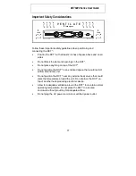
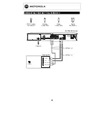
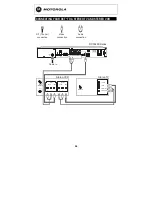
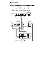
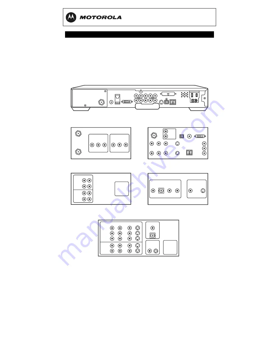
RECORDING YOUR CONNECTIONS
Use this diagram to record connections between your home
entertainment components. Later, you can use this diagram to reconnect
your system if you move the equipment or add new equipment.
Disconnect the power from the DCT* before connecting or changing
cable connections. Do not place another component or object on top of
the DCT*.
COAX
DIGITAL
ANALOG
R
L
AUDIO OUT
OPTICAL
VIDEO
S-VIDEO
VIDEO OUT
To TV
CABLE/
ANTENNA IN
INPUT
AUDIO
L
R
VIDEO
OUTPUT
AUDIO
L
R
VIDEO
DCT6400 Series
AUDIO OUT
AUDIO IN
TV
Pass Card
VIDEO
PRINTER
R
IN
L
OUT
S-VIDEO
IEEE 1394
OPTICAL
SPDIF
SPDIF
Y
Pb
Pr
ETHERNET
USB
IR
DVI-D OUT
CABLE
IN
VCR
DIGITAL INPUT
TV/MONITOR
OUTPUT
SPEAKER
CONNECTORS
COAX
VIDEO S-VIDEO
R
DVD
CABLE/TV
VIDEO 2
IN
OUT
VCR
AUDIO
VIDEO
L
VIDEO
S-VIDEO
OPTICAL
A/V receiver
DVD
IN
OUT
TAPE 1
R
CD IN
AUX IN
L
SPEAKER
CONNECTORS
Stereo receiver
HDTV / SDTV
CABLE/
ANTENNA IN
L
R
S-VIDEO IN
S-VIDEO OUT
VIDEO IN
AUDIO IN
AUDIO OUT
VIDEO OUT
L/MONO
R
Y
Pb
Pr
IEEE 1394
OPTICAL
SPDIF
SPDIF
DVI-HDTV


