20-26
MC9328MX1 Reference Manual
MOTOROLA
Multimedia Card/Secure Digital Host Controller Module (MMC/SD)
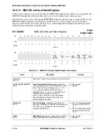
20.6.10 MMC/SD Interrupt Mask Register
When certain conditions exist in the module, the MMC/SD module has the ability to set an interrupt. The
MMC/SD Interrupt Mask Register allows the user to control whether these interrupts occur.
Rewriting this register clears the interrupt MMC_IRQ. When the interrupt source is from the SD I/O, the
MMC/SD module continues to interrupt the system. In this case, the user must write to the internal
registers on the SD I/O card. This is the only way to acknowledge the interrupt. In the interrupt service
routine the status indicators should be polled.
INT_MASK
MMC/SD Interrupt Mask Register
Addr
0x00214024
BIT
31
30
29
28
27
26
25
24
23
22
21
20
19
18
17
16
TYPE
r
r
r
r
r
r
r
r
r
r
r
r
r
r
r
r
RESET
0
0
0
0
0
0
0
0
0
0
0
0
0
0
0
0
0x0000
BIT
15
14
13
12
11
10
9
8
7
6
5
4
3
2
1
0
AUTO_
CARD_
DETECT
DAT0
_EN
SDIO
BUF_
READY
END_
CMD_
RES
WRITE
_OP_
DONE
DATA_
TRAN
TYPE
r
r
r
r
r
r
r
r
r
rw
rw
rw
rw
rw
rw
rw
RESET
0
0
0
0
0
0
0
0
0
0
0
0
0
0
0
0
0x0000
Table 20-14. MMC/SD Interrupt Mask Register Description
Name
Description
Settings
Reserved
Bits 31–7
Reserved—These bits are reserved and should read 0.
AUTO_CARD_DETECT
Bit 6
Auto Card Detect (SD card only)
—Masks the
auto card detect interrupt. Card insertion results in
the SD_DAT [3:0] pins changing from
0111
to
1111
, and card removal results in the pins
changing from
1111
to
0111
. After the card is
detected, the user program must mask
AUTO_CARD_DETECT to avoid misleading
interrupt generation while the SD_DAT lines
change during card access.
0 = Not masked
1 = Masked
DAT0_EN
Bit 5
SD_DAT0 Enable
—Identifies how the SD I/O
interrupt is detected. An interrupt is determined by
SD_DAT [1] = 0, however this bit is an optional
setting for the SDIO bit.
0 = SD I/O’s Interrupt detection
based on SD_DAT [3:1] =
110
1 = SD I/O’s Interrupt detection
based on SD_DAT [3:0] =
1101
SDIO
Bit 4
MMC/SD I/O
—Masks the interrupt from the SD I/O
card to the MMC/SD module I/O interrupt mask.
0 = Not masked
1 = Masked
Summary of Contents for DragonBall MC9328MX1
Page 68: ...1 12 MC9328MX1 Reference Manual MOTOROLA Introduction ...
Page 86: ...2 18 MC9328MX1 Reference Manual MOTOROLA Signal Descriptions and Pin Assignments ...
Page 116: ...3 30 MC9328MX1 Reference Manual MOTOROLA Memory Map ...
Page 126: ...4 10 MC9328MX1 Reference Manual MOTOROLA ARM920T Processor ...
Page 160: ...8 8 MC9328MX1 Reference Manual MOTOROLA System Control ...
Page 272: ...13 32 MC9328MX1 Reference Manual MOTOROLA DMA Controller ...
Page 281: ...Programming Model MOTOROLA Watchdog Timer Module 14 9 ...
Page 282: ...14 10 MC9328MX1 Reference Manual MOTOROLA Watchdog Timer Module ...
Page 300: ...15 18 MC9328MX1 Reference Manual MOTOROLA Analog Signal Processor ASP ...
Page 438: ...18 16 MC9328MX1 Reference Manual MOTOROLA Serial Peripheral Interface Modules SPI 1 and SPI 2 ...
Page 478: ...19 40 MC9328MX1 Reference Manual MOTOROLA LCD Controller ...
Page 574: ...21 32 MC9328MX1 Reference Manual MOTOROLA Memory Stick Host Controller MSHC Module ...
Page 598: ...23 16 MC9328MX1 Reference Manual MOTOROLA Real Time Clock RTC ...
Page 670: ...24 72 MC9328MX1 Reference Manual MOTOROLA SDRAM Memory Controller ...
Page 726: ...25 56 MC9328MX1 Reference Manual MOTOROLA SmartCard Interface Module SIM ...
Page 736: ...26 10 MC9328MX1 Reference Manual MOTOROLA General Purpose Timers ...
Page 854: ...29 18 MC9328MX1 Reference Manual MOTOROLA I2C Module ...
Page 900: ...30 46 MC9328MX1 Reference Manual MOTOROLA Synchronous Serial Interface SSI ...
Page 942: ...32 26 MC9328MX1 Reference Manual MOTOROLA GPIO Module and I O Multiplexer IOMUX ...

