20-60
MC9328MX1 Reference Manual
MOTOROLA
Multimedia Card/Secure Digital Host Controller Module (MMC/SD)
20.7.8.5 Response Formats
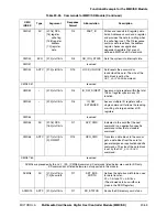
Table 20-25 on page 20-56 lists all commands supported by the MMC/SD module and their response
formats. All responses are sent via the command line SD_CMD. The response transmission always starts
with the left bit of the bit stream corresponding to the response codeword. The code length depends on the
response type.
The first two bits of the response are the start bit and the direction bit. The second bit indicates the
direction of transmission. Other response bits are dependent on the type of response.
Table 20-26 through Table 20-32 describe the command response formats. In the tables a value denoted by
x
indicates a variable entry. All responses except for type R3 are protected by a CRC. Every command
codeword is terminated by the end bit.
20.7.8.5.1 R1—Normal Response
•
Response length is 48 bits
•
Bits 45:40 contain the binary-coded number of the command index generating the response
•
The status of the card is coded in 32 bits (Card Status Register)
NOTE:
When data transfer to the card is involved, a busy signal can appear on the
data line after the transmission of each block of data. The MMC/SD
module must check for busy after data block transmission.
ACMD22
ADTC
[31:0] stuff bits
R1
SEND_NUM_
WR_SECTORS
Sends the number of written (without
errors) sectors. Responds with 32
bit + CRC data block.
ACMD23
AC
[31:23] stuff bits
[22:0] number
of blocks
R1
SET_WR_BLK
_ERASE
_COUNT
Sets the number of write blocks to be
pre-erased before writing (used for
faster execution of the
WRITE_MULTIPLE_BLOCK (CMD
25). 1 = default (one write block).
ACMD41
BCR
[31:0] OCR
R3
SD_APP_OP
_COND
Asks the accessed card to send its
operating condition register (OCR)
content on the SD_CMD line.
ACMD42
AC
[31:1] stuff bits
[0] SET_CD
R1
SET_CLR_
CARD_DETECT
Connects (1) or disconnects (0) the 50
kOhm pull-up resistor on the
CD/SD_DAT [3] (pin 1) of the card.
The pull-up is used for card detection.
ACMD51
ADTC
[31:0] stuff bits
R1
SEND_SCR
Reads the SD Configuration Register.
1.
1
—The MMC/SD module receives a block of data from the card
0
—The MMC/SD module sends a block of data to the card
Table 20-25. Commands for MMC/SD Module (Continued)
CMD
INDEX
Type
Argument
Response
Format
Abbreviation
Description
Summary of Contents for DragonBall MC9328MX1
Page 68: ...1 12 MC9328MX1 Reference Manual MOTOROLA Introduction ...
Page 86: ...2 18 MC9328MX1 Reference Manual MOTOROLA Signal Descriptions and Pin Assignments ...
Page 116: ...3 30 MC9328MX1 Reference Manual MOTOROLA Memory Map ...
Page 126: ...4 10 MC9328MX1 Reference Manual MOTOROLA ARM920T Processor ...
Page 160: ...8 8 MC9328MX1 Reference Manual MOTOROLA System Control ...
Page 272: ...13 32 MC9328MX1 Reference Manual MOTOROLA DMA Controller ...
Page 281: ...Programming Model MOTOROLA Watchdog Timer Module 14 9 ...
Page 282: ...14 10 MC9328MX1 Reference Manual MOTOROLA Watchdog Timer Module ...
Page 300: ...15 18 MC9328MX1 Reference Manual MOTOROLA Analog Signal Processor ASP ...
Page 438: ...18 16 MC9328MX1 Reference Manual MOTOROLA Serial Peripheral Interface Modules SPI 1 and SPI 2 ...
Page 478: ...19 40 MC9328MX1 Reference Manual MOTOROLA LCD Controller ...
Page 574: ...21 32 MC9328MX1 Reference Manual MOTOROLA Memory Stick Host Controller MSHC Module ...
Page 598: ...23 16 MC9328MX1 Reference Manual MOTOROLA Real Time Clock RTC ...
Page 670: ...24 72 MC9328MX1 Reference Manual MOTOROLA SDRAM Memory Controller ...
Page 726: ...25 56 MC9328MX1 Reference Manual MOTOROLA SmartCard Interface Module SIM ...
Page 736: ...26 10 MC9328MX1 Reference Manual MOTOROLA General Purpose Timers ...
Page 854: ...29 18 MC9328MX1 Reference Manual MOTOROLA I2C Module ...
Page 900: ...30 46 MC9328MX1 Reference Manual MOTOROLA Synchronous Serial Interface SSI ...
Page 942: ...32 26 MC9328MX1 Reference Manual MOTOROLA GPIO Module and I O Multiplexer IOMUX ...


