Functional Description
MOTOROLA
SmartCard Interface Module (SIM)
25-9
The transmit NACK generator is also responsible for keeping track of the number of NACKs received
during a transmit operation. The SIM receive state machine detects NACKs generated by the SmartCard,
and reports them to the transmit NACK logic. Once the number of detected NACKs has reached the
programmed threshold, an interrupt flag is generated, the transmit FIFO is flushed, and the transmitter is
disabled. Section 25.2.2, “SIM Transmitter,” on page 25-2 describes the NACK threshold operation based
on the programmed value of the XTH bits in the XMT_THRESHOLD register.
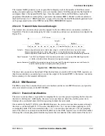
25.3.2.6 Transmit Data Convention Logic
The transmit data convention logic provides support for the two different data conventions available in
SmartCards. The data conventions parity bit, direct convention, and inverse convention and are depicted in
Figure 25-6.
Figure 25-6. SIM Data Conventions
The direct data convention is the default. When the data format control bit (IC) in the CNTL register is set,
then the transmit data convention logic converts the output of the transmit FIFO to the inverse convention
before sending it to the transmit shift register.
25.3.3 SIM Receiver
The SIM receiver block contains the receive state machine and the receive FIFO functions, and provides
all receive related circuitry of the MC9328MX1.
25.3.3.1 Receive State Machine
The receive state machine is responsible for sampling the receive data pin and capturing the bit value into
the receive shift register. Additionally, the receive state machine can detect the start bit, parity errors,
framing errors, and initial character when operating in initial character mode.
Once enabled by the RCV_EN bit in the ENABLE register, the receive state machine sequences through
the states as shown in Figure 25-7. The states identified with a “16x” are used when operating in a 16X
oversampling mode. The states identified with a “12x” are used when operating in a 12X oversampling
mode. This mode is used only when the BAUD_SEL bits in the CNTL register are set to 000. The number
following the oversampling mode identifier represents the state number in the current mode. There are 12
Parity Bit:
When configured for even parity, total number of logic 1s in the 9 bits (8 bits data, 1 parity bit) is even.
When configured for odd parity, total number of logic 1s in the 9 bits (8 bits data, 1 parity bit) is odd.
When configured for inverse convention, the parity bit is inverted by the SmartCard before being transmitte
Direct Convention: The LSB (Least Significant Bit) of the data byte to be sent is
ba,
and the MSB (Most Significant Bit
bh
. Neither of the data bits nor the parity bit are logically inverted.
Inverse Convention: The MSB of the data byte to be sent is
ba
, and the LSB of the data byte to be sent is
bh
. Both of th
data bits and the parity bit are logically inverted by hardware.
Start ba
bb
bc
bd
be
bf
bg
bh
P
Stop Bits
ba
bb
bc
bd
be
Start
Parity Bit
Byte
i
Byte
i+1
12 ETUs min
Summary of Contents for DragonBall MC9328MX1
Page 68: ...1 12 MC9328MX1 Reference Manual MOTOROLA Introduction ...
Page 86: ...2 18 MC9328MX1 Reference Manual MOTOROLA Signal Descriptions and Pin Assignments ...
Page 116: ...3 30 MC9328MX1 Reference Manual MOTOROLA Memory Map ...
Page 126: ...4 10 MC9328MX1 Reference Manual MOTOROLA ARM920T Processor ...
Page 160: ...8 8 MC9328MX1 Reference Manual MOTOROLA System Control ...
Page 272: ...13 32 MC9328MX1 Reference Manual MOTOROLA DMA Controller ...
Page 281: ...Programming Model MOTOROLA Watchdog Timer Module 14 9 ...
Page 282: ...14 10 MC9328MX1 Reference Manual MOTOROLA Watchdog Timer Module ...
Page 300: ...15 18 MC9328MX1 Reference Manual MOTOROLA Analog Signal Processor ASP ...
Page 438: ...18 16 MC9328MX1 Reference Manual MOTOROLA Serial Peripheral Interface Modules SPI 1 and SPI 2 ...
Page 478: ...19 40 MC9328MX1 Reference Manual MOTOROLA LCD Controller ...
Page 574: ...21 32 MC9328MX1 Reference Manual MOTOROLA Memory Stick Host Controller MSHC Module ...
Page 598: ...23 16 MC9328MX1 Reference Manual MOTOROLA Real Time Clock RTC ...
Page 670: ...24 72 MC9328MX1 Reference Manual MOTOROLA SDRAM Memory Controller ...
Page 726: ...25 56 MC9328MX1 Reference Manual MOTOROLA SmartCard Interface Module SIM ...
Page 736: ...26 10 MC9328MX1 Reference Manual MOTOROLA General Purpose Timers ...
Page 854: ...29 18 MC9328MX1 Reference Manual MOTOROLA I2C Module ...
Page 900: ...30 46 MC9328MX1 Reference Manual MOTOROLA Synchronous Serial Interface SSI ...
Page 942: ...32 26 MC9328MX1 Reference Manual MOTOROLA GPIO Module and I O Multiplexer IOMUX ...


