Programming Model
MOTOROLA
USB Device Port
28-27
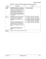
FRAME3
Bit 24
Frame Status Bit 3
—Indicates whether a frame boundary
exists in bus bits [7:0] for non-DMA applications.
0 = No frame boundary on the [7:0]
byte
1 = A frame boundary has occurred
on the [7:0] byte of the bus
Reserved
Bit 23
Reserved—This bit is reserved and should read 0.
ERROR
Bit 22
FIFO Error
—Signifies that an error condition has happened in
the FIFO controller. Writing 1 to ERROR clears it. Writing 0
has no effect.
0 = No error
1 = Underflow, overflow, pointer
out of bounds, or other error
condition occurred
UF
Bit 21
FIFO Underflow
—Indicates FIFO underflow status. Writing 1
to UF clears it. Writing 0 has no effect.
0 = No underflow
1 = Read pointer has passed the
write pointer
OF
Bit 20
FIFO Overflow
—Indicates FIFO overflow status. Writing 1 to
OF clears it. Writing 0 has no effect.
0 = No overflow
1 = Write pointer has passed the
read pointer
FR
Bit 19
Frame Ready
—Indicates frame ready status. FR is inactive
when the FIFO is not programmed for frame mode.
0 = No complete frames exist in the
FIFO
1 = One or more complete frames
exists in the FIFO
FULL
Bit 18
FIFO Full
—Indicates FIFO full status. Read FULL to clear it.
0 = The FIFO is not full
1 = The FIFO is full
ALARM
Bit 17
FIFO Alarm
—Indicates FIFO alarm status. The specific alarm
condition detected depends on the FIFO direction. The signal
relies on the values of the alarm (ALRM) field of the Endpoint n
FIFO Alarm Register and the granularity (GR) field of the
Endpoint n FIFO Control Register.
For IN (transmit) FIFOs, the ALARM bit indicates a low level. It
asserts when there are less than ALRM bytes of data
remaining in the FIFO, and deasserts when there are less than
4 times GR free bytes remaining.
When the FIFO is configured to receive (OUT FIFOs), the
ALARM bit indicates a high level. It asserts when there are
less than ALRM bytes free in the FIFO, and deasserts when
there are less than GR bytes of data remaining.
This signal is cleared by reading or writing (as appropriate) the
FIFO, or by manipulating the FIFO pointers.
0 = The alarm not set
1 = The alarm is set
EMPTY
Bit 16
FIFO Empty
—Indicates FIFO empty status. Write 1 to EMPTY
to clear it.
0 = The FIFO is not empty
1 = The FIFO is empty
Reserved
Bits 15–0
Reserved—These bits are reserved and should read 0.
Table 28-18. Endpoint n FIFO Status Registers Description (Continued)
Name
Description
Settings
Summary of Contents for DragonBall MC9328MX1
Page 68: ...1 12 MC9328MX1 Reference Manual MOTOROLA Introduction ...
Page 86: ...2 18 MC9328MX1 Reference Manual MOTOROLA Signal Descriptions and Pin Assignments ...
Page 116: ...3 30 MC9328MX1 Reference Manual MOTOROLA Memory Map ...
Page 126: ...4 10 MC9328MX1 Reference Manual MOTOROLA ARM920T Processor ...
Page 160: ...8 8 MC9328MX1 Reference Manual MOTOROLA System Control ...
Page 272: ...13 32 MC9328MX1 Reference Manual MOTOROLA DMA Controller ...
Page 281: ...Programming Model MOTOROLA Watchdog Timer Module 14 9 ...
Page 282: ...14 10 MC9328MX1 Reference Manual MOTOROLA Watchdog Timer Module ...
Page 300: ...15 18 MC9328MX1 Reference Manual MOTOROLA Analog Signal Processor ASP ...
Page 438: ...18 16 MC9328MX1 Reference Manual MOTOROLA Serial Peripheral Interface Modules SPI 1 and SPI 2 ...
Page 478: ...19 40 MC9328MX1 Reference Manual MOTOROLA LCD Controller ...
Page 574: ...21 32 MC9328MX1 Reference Manual MOTOROLA Memory Stick Host Controller MSHC Module ...
Page 598: ...23 16 MC9328MX1 Reference Manual MOTOROLA Real Time Clock RTC ...
Page 670: ...24 72 MC9328MX1 Reference Manual MOTOROLA SDRAM Memory Controller ...
Page 726: ...25 56 MC9328MX1 Reference Manual MOTOROLA SmartCard Interface Module SIM ...
Page 736: ...26 10 MC9328MX1 Reference Manual MOTOROLA General Purpose Timers ...
Page 854: ...29 18 MC9328MX1 Reference Manual MOTOROLA I2C Module ...
Page 900: ...30 46 MC9328MX1 Reference Manual MOTOROLA Synchronous Serial Interface SSI ...
Page 942: ...32 26 MC9328MX1 Reference Manual MOTOROLA GPIO Module and I O Multiplexer IOMUX ...


