DSP Core Programming Model
Host Interface (HI08)
6
-21
6.6.7
Host Transmit (HTX) Register
The HTX register is used in DSP-to-host data transfers. The DSP56303 views it as a 24-bit
write-only register. Its address is X:$FFFFC7. Writing to the HTX register clears the host
transfer data empty bit (HSR[HTDE]) on the DSP side. The contents of the HTX register are
transferred as 24-bit data to the Receive Data Registers (RXH:RXM:RXL) when both
HSR[HTDE] and receive data full (ISR[RXDF]) on the host-side bits are cleared. This
transfer operation sets the ISR[RXDF] and HSR[HTDE] bits. The DSP56303 can set the
HCR[HTIE] bit to cause a host transmit data interrupt when HSR[HTDE] is set. To prevent
the previous data from being overwritten, the DSP56303 should never write to the HTX when
HSR[HTDE] is cleared.
Note:
When data is written to a peripheral device, there is a two-cycle pipeline delay until
any status bits affected by this operation are updated. If you read any of the status
bits within the next two cycles, the bit does not reflect its current status. For details,
see Section 5.4.1, Polling, on page 5-3.
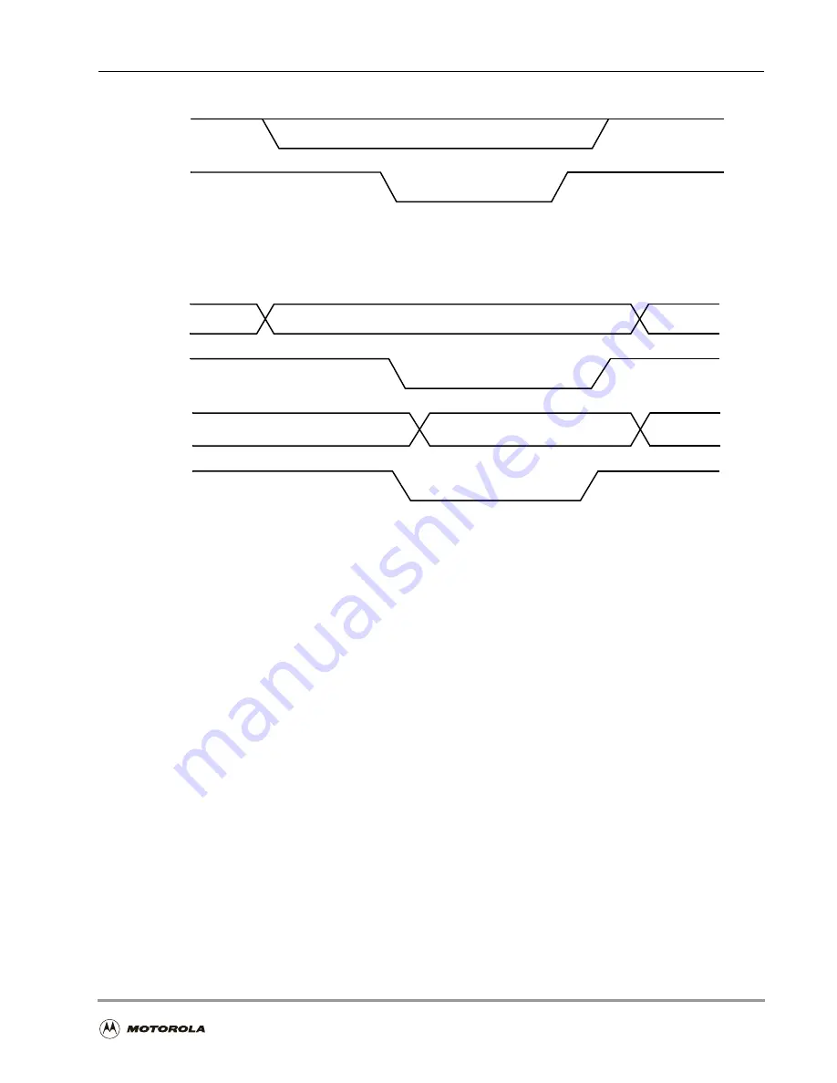
Figure 6-13. Single-Strobe Mode
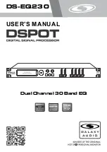
Figure 6-14. Dual-Strobe Mode
HRW
HDS
In a single-strobe mode, a DS (data strobe) signal qualifies the access, while a R/W (Read-Write)
signal specifies the direction of the access.
Data
HWR
Data
HRD
In dual-strobe mode, separate HRD and HWR signals specify the access as a read or write
access, respectively.
Read Data Out
Read Cycle
Write Cycle
Write Data In
Summary of Contents for DSP56303
Page 1: ...DSP56303 User s Manual 24 Bit Digital Signal Processor DSP56303UM AD Revision 1 January 2001 ...
Page 52: ...JTAG OnCE Interface 2 22 DSP56303 User s Manual ...
Page 114: ...General Purpose Input Output GPIO 5 10 DSP56303 User s Manual ...
Page 212: ...GPIO Signals and Registers 8 26 DSP56303 User s Manual ...
Page 268: ...Interrupt Equates A 22 DSP56303 User s Manual ...
Page 306: ...Programming Sheets B 38 DSP56303 User s Manual ...
Page 320: ...Index 14 DSP56303 User s Manual ...


