


ESSI Programming Model
7
-32
DSP56303 User’s Manual
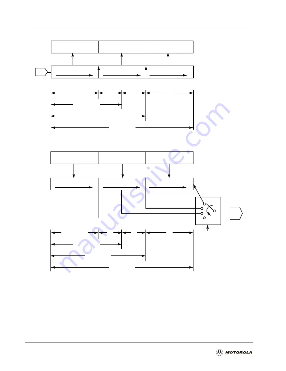
Figure 7-13. ESSI Data Path Programming Model (SHFD = 1)
SR
ESSI Receive Data
Register (Read Only)
ESSI Receive
Shift Register
24-bit Data
0
0
0
16-bit Data
12-bit Data
8-bit Data
LSB
LSB
LSB
LSB
MSB
MSB
MSB
MSB
Least Significant
Zero Fill
(a) Receive Registers
ST
ESSI Transmit Data
Register
(Write Only)
ESSI Transmit Shift
Register
24 Bit
WL1, WL0
24-bit Data
0
0
0
16-bit Data
12-bit Data
8-bit Data
LSB
LSB
LSB
LSB
MSB
MSB
MSB
MSB
Least Significant
Zero Fill
16 Bit
12 Bit
8 Bit
(b) Transmit Registers
Receive High Byte
Receive Middle Byte
Receive Low Byte
Receive High Byte
Receive Middle Byte
Receive Low Byte
23
16 15
8 7
0
23
16 15
7
0
7
0 7
7
0
7
0 7
0 7
0
NOTES:
Data is received MSB first if SHFD = 0.
24-bit fractional format (ALC = 0).
32-bit mode is not shown.
Transmit High Byte
Transmit Middle Byte
Transmit Low Byte
Transmit High Byte
Transmit Middle Byte
Transmit Low Byte
23
16 15
8 7
0
23
16 15
7
0
7
0 7
7
0
7
0 7
0 7
0
NOTES:
Data is received MSB first if SHFD = 0.
4-bit fractional format (ALC = 0).
32-bit mode is not shown.
0
0
0
0
Summary of Contents for DSP56303
Page 1: ...DSP56303 User s Manual 24 Bit Digital Signal Processor DSP56303UM AD Revision 1 January 2001 ...
Page 52: ...JTAG OnCE Interface 2 22 DSP56303 User s Manual ...
Page 114: ...General Purpose Input Output GPIO 5 10 DSP56303 User s Manual ...
Page 212: ...GPIO Signals and Registers 8 26 DSP56303 User s Manual ...
Page 268: ...Interrupt Equates A 22 DSP56303 User s Manual ...
Page 306: ...Programming Sheets B 38 DSP56303 User s Manual ...
Page 320: ...Index 14 DSP56303 User s Manual ...


