


Operating Modes
Triple Timer Module
9
-23
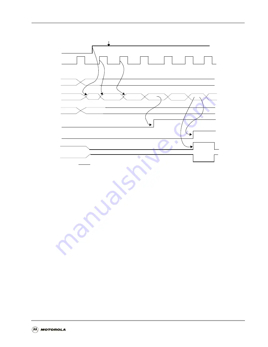
Figure 9-18. Watchdog Pulse Mode
Mode 9 (internal clock): TRM = 0
N = write preload
M = write compare
TE
Clock
(CLK/2 or prescale CLK)
TLR
TCF (Compare Interrupt if TCIE = 1)
Counter (TCR)
first event
M
0
N
M
1
N
TRM = 1 is not useful for watchdog function
0
M + 1
TOF (Overflow Interrupt if TOIE = 1)
TIO pin (INV = 0)
TIO pin (INV = 1)
(Software does not reset watchdog timer; watchdog times out)
N + 1
pulse width
= timer
clock period
float
float
low
high
TIO can connect to the RESET pin, internal hardware preserves the TIO value and
direction for an additional 2.5 clocks to ensure a reset of valid length.
TCPR
Summary of Contents for DSP56303
Page 1: ...DSP56303 User s Manual 24 Bit Digital Signal Processor DSP56303UM AD Revision 1 January 2001 ...
Page 52: ...JTAG OnCE Interface 2 22 DSP56303 User s Manual ...
Page 114: ...General Purpose Input Output GPIO 5 10 DSP56303 User s Manual ...
Page 212: ...GPIO Signals and Registers 8 26 DSP56303 User s Manual ...
Page 268: ...Interrupt Equates A 22 DSP56303 User s Manual ...
Page 306: ...Programming Sheets B 38 DSP56303 User s Manual ...
Page 320: ...Index 14 DSP56303 User s Manual ...


