7-26
DSP56305 User’s Manual
MOTOROLA
Enhanced Synchronous Serial Interface (ESSI)
ESSI Programming Model
7.4.2.12
ESSI Mode Select (MOD) CRB Bit 13
MOD selects the operational mode of the ESSI (see Figure 7-18). When MOD is cleared,
the Normal mode is selected; when MOD is set, the Network mode is selected. In the
Normal mode, the frame rate divider determines the word transfer rate: one word is
transferred per frame sync during the frame sync time slot. In Network mode, a word
may be transferred every time slot. For more details, see
Section 7.5
. Either a hardware
reset signal or a software reset instruction will clear MOD.
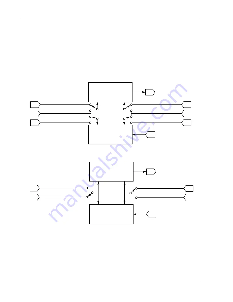
Figure 7-17
CRB SYN Bit Operation
External Frame SYNC
SC1
Asynchronous (SYN = 0)
Transmitter
Clock
Frame
SYNC
RECEIVER
Clock
Frame
SYNC
SRD
STD
SC2
External Transmit Frame SYNC
External Receive Frame SYNC
Internal Frame SYNC
SC0
SCK
External Transmit Clock
External Receive Clock
Internal Clock
ESSI Bit
Clock
NOTE: Transmitter and receiver may have different clocks and frame syncs.
SYNCHRONOUS (SYN = 1)
Transmitter
Clock
Frame
SYNC
Receiver
Clock
Frame
SYNC
SRD
STD
SC2
Internal Frame SYNC
SCK
External Clock
Internal Clock
ESSI Bit
Clock
NOTE: Transmitter and receiver may have the same clock frame syncs.
AA0682
Summary of Contents for DSP56305
Page 34: ...xxxii DSP56305 User s Manual MOTOROLA ...
Page 40: ...xxxvi DSP56305 User s Manual MOTOROLA ...
Page 41: ...MOTOROLA DSP56305 User s Manual 1 1 SECTION 1 DSP56305 OVERVIEW ...
Page 58: ...1 18 DSP56305 User s Manual MOTOROLA DSP56305 Overview DSP56305 Architecture Overview ...
Page 59: ...MOTOROLA DSP56305 User s Manual 2 1 SECTION 2 SIGNAL CONNECTION DESCRIPTIONS ...
Page 98: ...2 40 DSP56305 User s Manual MOTOROLA Signal Connection Descriptions JTAG OnCE Interface ...
Page 99: ...MOTOROLA DSP56305 User s Manual 3 1 SECTION 3 MEMORY CONFIGURATION ...
Page 119: ...MOTOROLA DSP56305 User s Manual 4 1 SECTION 4 CORE CONFIGURATION ...
Page 144: ...4 26 DSP56305 User s Manual MOTOROLA Core Configuration JTAG Boundary Scan Register BSR ...
Page 145: ...MOTOROLA DSP56305 User s Manual 5 1 SECTION 5 GENERAL PURPOSE I O ...
Page 149: ...HOST INTERFACE HI32 MOTOROLA DSP56305 User s Manual 6 1 SECTION 6 HOST INTERFACE HI32 ...
Page 150: ...6 2 DSP56305 User s Manual MOTOROLA HOST INTERFACE HI32 ...
Page 259: ...MOTOROLA DSP56305 User s Manual 7 1 SECTION 7 ENHANCED SYNCHRONOUS SERIAL INTERFACE ESSI ...
Page 315: ...MOTOROLA DSP56305 User s Manual 8 1 SECTION 8 SERIAL COMMUNICATION INTERFACE SCI ...
Page 347: ...MOTOROLA DSP56305 User s Manual 9 1 SECTION 9 TIMER EVENT COUNTER ...
Page 376: ...9 30 DSP56305 User s Manual MOTOROLA Timer Event Counter Timer Modes of Operation ...
Page 377: ...MOTOROLA DSP56305 User s Manual 10 1 SECTION 10 ON CHIP EMULATION MODULE ...
Page 411: ...MOTOROLA DSP56305 User s Manual 11 1 SECTION 11 JTAG PORT ...
Page 430: ...11 20 DSP56305 User s Manual MOTOROLA JTAG Port DSP56305 Boundary Scan Register ...
Page 431: ...Filter Co Processor MOTOROLA DSP56305 User s Manual 12 1 SECTION 12 FILTER CO PROCESSOR ...
Page 471: ...VITERBI CO PROCESSOR MOTOROLA DSP56305 User s Manual 13 1 SECTION 13 VITERBI CO PROCESSOR ...
Page 522: ...13 52 DSP56305 User s Manual MOTOROLA VITERBI CO PROCESSOR References ...
Page 554: ...14 32 DSP56305 User s Manual MOTOROLA CYCLIC CODE CO PROCESSOR Configuration Examples ...
Page 555: ...MOTOROLA DSP56305 User s Manual A 1 APPENDIX A BOOTSTRAP CODE ...
Page 568: ...A 14 DSP56305 User s Manual MOTOROLA Bootstrap Code ...
Page 569: ...Equates MOTOROLA DSP56305 User s Manual B 1 APPENDIX B EQUATES ...
Page 589: ...MOTOROLA DSP56305 User s Manual C 1 APPENDIX C JTAG BSDL ...
Page 590: ...C 2 DSP56305 User s Manual MOTOROLA JTAG BSDL ...
Page 600: ...C 12 DSP56305 User s Manual MOTOROLA JTAG BSDL ...
Page 601: ...MOTOROLA DSP56305 User s Manual D 1 APPENDIX D PROGRAMMING REFERENCE ...
Page 602: ...D 2 DSP56305 User s Manual MOTOROLA PROGRAMMING REFERENCE ...
Page 661: ...Y MOTOROLA DSP56305 User s Manual Index 11 ...
Page 662: ...Y Index 12 DSP56305 User s Manual MOTOROLA ...


