11-12
DSP56305 User’s Manual
MOTOROLA
JTAG Port
DSP56300 Restrictions
11.3.2.8
BYPASS (B[3:0] = 1111)
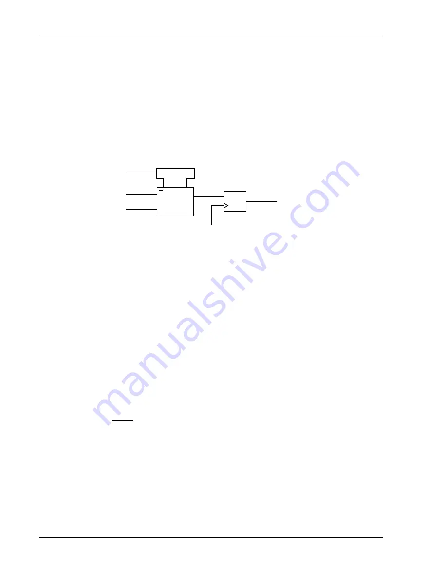
The BYPASS instruction selects the single-bit Bypass register, as shown in Figure 11-5.
This creates a shift-register path from TDI to the Bypass register, and finally to TDO,
circumventing the BSR. This instruction is used to enhance test efficiency when a
component other than the DSP56300 core-based device becomes the device under test.
When the Bypass register is selected by the current instruction, the shift-register stage is
set to a logic 0 on the rising edge of TCK in the Capture-DR controller state. Therefore,
the first bit shifted out after selecting the Bypass register is always a logic 0.
11.4
DSP56300 RESTRICTIONS
The control afforded by the output enable signals using the BSR and the EXTEST
instruction requires a compatible circuit-board test environment to avoid
device-destructive configurations. The user must avoid situations in which the
DSP56300 core output drivers are enabled into actively driven networks. In addition, the
EXTEST instruction can be performed only after power-up or regular hardware reset
while EXTAL was provided. Then during the execution of EXTEST, EXTAL can remain
inactive.
There are two constraints related to the JTAG interface. First, the TCK input does not
include an internal pullup resistor and should not be left unconnected. The second
constraint is to ensure that the JTAG test logic is kept transparent to the system logic by
forcing the TAP into the Test-Logic-Reset controller state, using either of two methods.
During power-up, TRST must be externally asserted to force the TAP controller into this
state. After power-up is concluded, TMS must be sampled as a logic 1 for five
consecutive TCK rising edges. If TMS either remains unconnected or is connected to
V
CC
, then the TAP controller cannot leave the Test-Logic-Reset state, regardless of the
state of TCK.
Figure 11-5
Bypass Register
1
1
Mux
G1
C
D
To TDO
From TDI
0
Shift DR
CLOCKDR
AA0115
Summary of Contents for DSP56305
Page 34: ...xxxii DSP56305 User s Manual MOTOROLA ...
Page 40: ...xxxvi DSP56305 User s Manual MOTOROLA ...
Page 41: ...MOTOROLA DSP56305 User s Manual 1 1 SECTION 1 DSP56305 OVERVIEW ...
Page 58: ...1 18 DSP56305 User s Manual MOTOROLA DSP56305 Overview DSP56305 Architecture Overview ...
Page 59: ...MOTOROLA DSP56305 User s Manual 2 1 SECTION 2 SIGNAL CONNECTION DESCRIPTIONS ...
Page 98: ...2 40 DSP56305 User s Manual MOTOROLA Signal Connection Descriptions JTAG OnCE Interface ...
Page 99: ...MOTOROLA DSP56305 User s Manual 3 1 SECTION 3 MEMORY CONFIGURATION ...
Page 119: ...MOTOROLA DSP56305 User s Manual 4 1 SECTION 4 CORE CONFIGURATION ...
Page 144: ...4 26 DSP56305 User s Manual MOTOROLA Core Configuration JTAG Boundary Scan Register BSR ...
Page 145: ...MOTOROLA DSP56305 User s Manual 5 1 SECTION 5 GENERAL PURPOSE I O ...
Page 149: ...HOST INTERFACE HI32 MOTOROLA DSP56305 User s Manual 6 1 SECTION 6 HOST INTERFACE HI32 ...
Page 150: ...6 2 DSP56305 User s Manual MOTOROLA HOST INTERFACE HI32 ...
Page 259: ...MOTOROLA DSP56305 User s Manual 7 1 SECTION 7 ENHANCED SYNCHRONOUS SERIAL INTERFACE ESSI ...
Page 315: ...MOTOROLA DSP56305 User s Manual 8 1 SECTION 8 SERIAL COMMUNICATION INTERFACE SCI ...
Page 347: ...MOTOROLA DSP56305 User s Manual 9 1 SECTION 9 TIMER EVENT COUNTER ...
Page 376: ...9 30 DSP56305 User s Manual MOTOROLA Timer Event Counter Timer Modes of Operation ...
Page 377: ...MOTOROLA DSP56305 User s Manual 10 1 SECTION 10 ON CHIP EMULATION MODULE ...
Page 411: ...MOTOROLA DSP56305 User s Manual 11 1 SECTION 11 JTAG PORT ...
Page 430: ...11 20 DSP56305 User s Manual MOTOROLA JTAG Port DSP56305 Boundary Scan Register ...
Page 431: ...Filter Co Processor MOTOROLA DSP56305 User s Manual 12 1 SECTION 12 FILTER CO PROCESSOR ...
Page 471: ...VITERBI CO PROCESSOR MOTOROLA DSP56305 User s Manual 13 1 SECTION 13 VITERBI CO PROCESSOR ...
Page 522: ...13 52 DSP56305 User s Manual MOTOROLA VITERBI CO PROCESSOR References ...
Page 554: ...14 32 DSP56305 User s Manual MOTOROLA CYCLIC CODE CO PROCESSOR Configuration Examples ...
Page 555: ...MOTOROLA DSP56305 User s Manual A 1 APPENDIX A BOOTSTRAP CODE ...
Page 568: ...A 14 DSP56305 User s Manual MOTOROLA Bootstrap Code ...
Page 569: ...Equates MOTOROLA DSP56305 User s Manual B 1 APPENDIX B EQUATES ...
Page 589: ...MOTOROLA DSP56305 User s Manual C 1 APPENDIX C JTAG BSDL ...
Page 590: ...C 2 DSP56305 User s Manual MOTOROLA JTAG BSDL ...
Page 600: ...C 12 DSP56305 User s Manual MOTOROLA JTAG BSDL ...
Page 601: ...MOTOROLA DSP56305 User s Manual D 1 APPENDIX D PROGRAMMING REFERENCE ...
Page 602: ...D 2 DSP56305 User s Manual MOTOROLA PROGRAMMING REFERENCE ...
Page 661: ...Y MOTOROLA DSP56305 User s Manual Index 11 ...
Page 662: ...Y Index 12 DSP56305 User s Manual MOTOROLA ...


