Specifications
Parallel Host Interface (HDI08) Timing
MOTOROLA
DSP56367
3-49
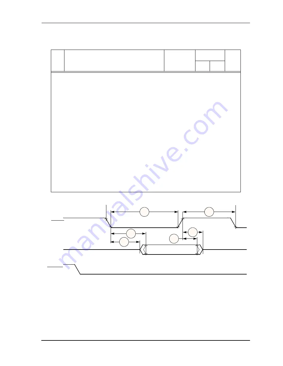
Figure 3-20 Host Interrupt Vector Register (IVR) Read Timing Diagram
Note:
1.
See Host Port Usage Considerations in the DSP56367 User’s Manual.
2.
In the timing diagrams below, the controls pins are drawn as active low. The pin
polarity is programmable.
3.
V
CC
= 1.8 V
±
5%; T
J
=
0°C to +95°C, C
L
= 50 pF
4.
The read data strobe is HRD in the dual data strobe mode and HDS in the single data
strobe mode.
5.
The “last data register” is the register at address $7, which is the last location to be
read or written in data transfers.
6.
This timing is applicable only if a read from the “last data register” is followed by a
read from the RXL, RXM, or RXH registers without first polling RXDF or HREQ
bits, or waiting for the assertion of the HOREQ signal.
7.
This timing is applicable only if two consecutive reads from one of these registers are
executed.
8.
The write data strobe is HWR in the dual data strobe mode and HDS in the single data
strobe mode.
9.
The data strobe is host read (HRD) or host write (HWR) in the dual data strobe mode
and host data strobe (HDS) in the single data strobe mode.
10. The host request is HOREQ in the single host request mode and HRRQ and HTRQ in
the double host request mode.
11. In this calculation, the host request signal is pulled up by a 4.7 k
Ω
resistor in the
open-drain mode.
Table 3-18 Host Interface (HDI08) Timing (Continued)
No.
Characteristics
3
Expression
120 MHz
Unit
Min
Max
HACK
HD7–HD0
HOREQ
329
317
318
328
326
327
AA1105
Summary of Contents for DSP56367
Page 16: ...xvi MOTOROLA CONTENTS Paragraph Number Title Page Number ...
Page 22: ...xxii MOTOROLA List of Figures Figure Number Title Page Number ...
Page 26: ...xxvi MOTOROLA List of Tables Table Number Title Page Number ...
Page 148: ...4 6 DSP56367 MOTOROLA Design Considerations PLL Performance Issues ...
Page 248: ...9 30 DSP56367 MOTOROLA Serial Host Interface SHI Programming Considerations ...
Page 306: ...10 58 DSP56367 MOTOROLA Enhanced Serial Audio Interface ESAI ESAI Initialization Examples ...
Page 389: ...Bootstrap ROM Contents MOTOROLA DSP56367 A 15 end ...
Page 390: ...A 16 DSP56367 MOTOROLA Bootstrap ROM Contents ...
Page 432: ...C 8 DSP56367 MOTOROLA JTAG BSDL ...
Page 484: ...D 52 DSP56367 MOTOROLA Programmer s Reference ...
Page 490: ...E 6 DSP56367 MOTOROLA Power Consumption Benchmark ...
Page 516: ...F 26 DSP56367 MOTOROLA IBIS Model ...
Page 522: ...Index 6 MOTOROLA Index ...
Page 523: ......


