Host Interface (HDI08)
HDI08 Block Diagram
MOTOROLA
DSP56367
8-5
8.4
HDI08 BLOCK DIAGRAM
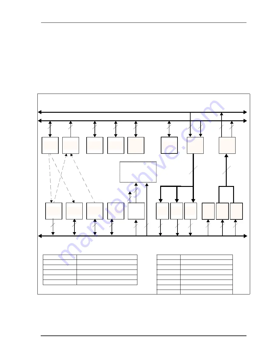
Figure 8-1 shows the HDI08 registers. The top row of registers (HCR, HSR, HDDR, HDR,
HBAR, HPCR, HOTX, HORX) can be accessed the DSP core. The bottom row of registers
(ISR, ICR, CVR, IVR, RXH:RXM:RXL and TXH:TXM:TXL) can be accessed by the host
processor.
Figure 8-1 HDI08 Block Diagram
RXL
TXM
TXH
8
HPCR
Latch
RXL
IVR
CVR
ICR
24
24
HDDR
HCR
HSR
HDR
24
24
24
24
24
DSP Peripheral Data Bus
8
8
8
8
8
8
5
3
HOST Bus
Address
Comparator
3
8
8
RXM
24
24
HBAR
ISR
8
HOR
HOT
24
Core DMA Data Bus
24
24
8
RXH
8
HCR
Host Control Register
HSR
Host Status Register
HPCR
Host Port Control Register
HBAR
Host Base Address register
HOTX
Host Transmit register
HORX
Host Receive register
HDDR
Host Data Direction Register
HDR
Host Data Register
ICR
Interface Control Register
CVR
Command Vector Register
ISR
Interface Status Register
IVR
Interrupt Vector Register
RXH/RXM/RXL
Receive Register High/Middle/Low
TXH/TXM/TXL
Transmit Register High/Middle/Low
Summary of Contents for DSP56367
Page 16: ...xvi MOTOROLA CONTENTS Paragraph Number Title Page Number ...
Page 22: ...xxii MOTOROLA List of Figures Figure Number Title Page Number ...
Page 26: ...xxvi MOTOROLA List of Tables Table Number Title Page Number ...
Page 148: ...4 6 DSP56367 MOTOROLA Design Considerations PLL Performance Issues ...
Page 248: ...9 30 DSP56367 MOTOROLA Serial Host Interface SHI Programming Considerations ...
Page 306: ...10 58 DSP56367 MOTOROLA Enhanced Serial Audio Interface ESAI ESAI Initialization Examples ...
Page 389: ...Bootstrap ROM Contents MOTOROLA DSP56367 A 15 end ...
Page 390: ...A 16 DSP56367 MOTOROLA Bootstrap ROM Contents ...
Page 432: ...C 8 DSP56367 MOTOROLA JTAG BSDL ...
Page 484: ...D 52 DSP56367 MOTOROLA Programmer s Reference ...
Page 490: ...E 6 DSP56367 MOTOROLA Power Consumption Benchmark ...
Page 516: ...F 26 DSP56367 MOTOROLA IBIS Model ...
Page 522: ...Index 6 MOTOROLA Index ...
Page 523: ......


