Host Interface (HDI08)
HDI08 – External Host Programmer’s Model
MOTOROLA
DSP56367
8-25
8.6.2
COMMAND VECTOR REGISTER (CVR)
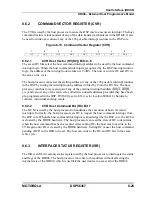
The CVR is used by the host processor to cause the DSP core to execute an interrupt. The host
command feature is independent of any of the data transfer mechanisms in the HDI08. It can
be used to invoke execution of any of the 128 possible interrupt routines in the DSP core.
8.6.2.1
CVR Host Vector (HV[6:0]) Bits 0–6
The seven HV bits select the host command interrupt address to be used by the host command
interrupt logic. When the host command interrupt is recognized by the DSP interrupt control
logic, the address of the interrupt routine taken is 2
∗
HV. The host can write HC and HV in
the same write cycle.
The host processor can select the starting address of any of the 128 possible interrupt routines
in the DSP by writing the interrupt routine address divided by 2 into the HV bits. The host
processor can thus force execution of any of the existing interrupt handlers (IRQA, IRQB,
etc.) and can use any of the reserved or otherwise unused addresses provided they have been
pre-programmed in the DSP. HV[6:0] is set to $32 (vector location $0064) by hardware,
software, individual and stop resets.
8.6.2.2
CVR Host Command Bit (HC) Bit 7
The HC bit is used by the host processor to handshake the execution of host command
interrupts. Normally, the host processor sets HC to request the host command interrupt from
the DSP core. When the host command interrupt is acknowledged by the DSP core, the HC bit
is cleared by the HDI08 hardware. The host processor can read the state of HC to determine
when the host command has been accepted. After setting HC, the host must not write to the
CVR again until HC is cleared by the HDI08 hardware. Setting HC causes the host command
pending (HCP) in the HSR to be set. The host can write to the HC and HV bits in the same
write cycle.
8.6.3
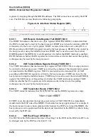
INTERFACE STATUS REGISTER (ISR)
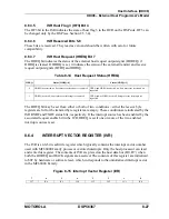
The ISR is an 8-bit read-only status register used by the host processor to interrogate the status
and flags of the HDI08. The host processor can write to this address without affecting the
internal state of the HDI08, which is useful if the user desires to access all of the HDI08
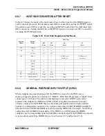
Figure 8-13 Command Vector Register (CVR)
7
6
5
4
3
2
1
0
HC
HV6
HV5
HV4
HV3
HV2
HV1
HV0
Summary of Contents for DSP56367
Page 16: ...xvi MOTOROLA CONTENTS Paragraph Number Title Page Number ...
Page 22: ...xxii MOTOROLA List of Figures Figure Number Title Page Number ...
Page 26: ...xxvi MOTOROLA List of Tables Table Number Title Page Number ...
Page 148: ...4 6 DSP56367 MOTOROLA Design Considerations PLL Performance Issues ...
Page 248: ...9 30 DSP56367 MOTOROLA Serial Host Interface SHI Programming Considerations ...
Page 306: ...10 58 DSP56367 MOTOROLA Enhanced Serial Audio Interface ESAI ESAI Initialization Examples ...
Page 389: ...Bootstrap ROM Contents MOTOROLA DSP56367 A 15 end ...
Page 390: ...A 16 DSP56367 MOTOROLA Bootstrap ROM Contents ...
Page 432: ...C 8 DSP56367 MOTOROLA JTAG BSDL ...
Page 484: ...D 52 DSP56367 MOTOROLA Programmer s Reference ...
Page 490: ...E 6 DSP56367 MOTOROLA Power Consumption Benchmark ...
Page 516: ...F 26 DSP56367 MOTOROLA IBIS Model ...
Page 522: ...Index 6 MOTOROLA Index ...
Page 523: ......


