10-8
DSP56367
MOTOROLA
Enhanced Serial Audio Interface (ESAI)
ESAI Data and Control Pins
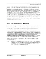
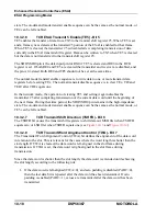
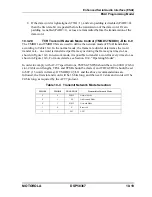
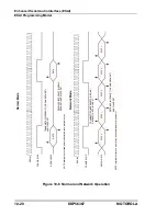
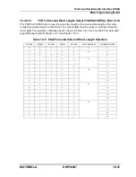
input flag IF1, the data value at the pin is stored in the IF1 bit in the SAISR register,
synchronized by the frame sync in normal mode or the slot in network mode.
FSR may be programmed as a general-purpose I/O pin (PC1) when the ESAI FSR function is
not being used.
10.2.10
FRAME SYNC FOR TRANSMITTER (FST)
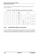
FST is a bidirectional pin providing the frame sync for both the transmitters and receivers in
the synchronous mode (SYN=1) and for the transmitters only in asynchronous mode (SYN=0)
(see Table 10-2). The direction of this pin is determined by the TFSD bit in the TCR register.
When configured as an output, this pin is the internally generated frame sync signal. When
configured as an input, this pin receives an external frame sync signal for the transmitters (and
the receivers in synchronous mode).
FST may be programmed as a general-purpose I/O pin (PC4) when the ESAI FST function is
not being used.
10.2.11
HIGH FREQUENCY CLOCK FOR TRANSMITTER (HCKT)
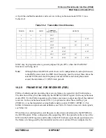
HCKT is a bidirectional pin providing the transmitters high frequency clock for the ESAI
interface. The direction of this pin is determined by the THCKD bit in the TCCR register. In
the asynchronous mode (SYN=0), the HCKT pin operates as the high frequency clock input or
output used by all enabled transmitters. In the synchronous mode (SYN=1), it operates as the
high frequency clock input or output used by all enabled transmitters and receivers. When
programmed as input this pin is used as an alternative high frequency clock source to the
ESAI transmitter rather than the DSP main clock. When programmed as output it can serve as
a high frequency sample clock (to external DACs for example) or as an additional system
clock. See Table 10-2.
HCKT may be programmed as a general-purpose I/O pin (PC5) when the ESAI HCKT
function is not being used.
10.2.12
HIGH FREQUENCY CLOCK FOR RECEIVER (HCKR)
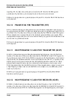
HCKR is a bidirectional pin providing the receivers high frequency clock for the ESAI
interface. The direction of this pin is determined by the RHCKD bit in the RCCR register. In
the asynchronous mode (SYN=0), the HCKR pin operates as the high frequency clock input
Summary of Contents for DSP56367
Page 16: ...xvi MOTOROLA CONTENTS Paragraph Number Title Page Number ...
Page 22: ...xxii MOTOROLA List of Figures Figure Number Title Page Number ...
Page 26: ...xxvi MOTOROLA List of Tables Table Number Title Page Number ...
Page 148: ...4 6 DSP56367 MOTOROLA Design Considerations PLL Performance Issues ...
Page 248: ...9 30 DSP56367 MOTOROLA Serial Host Interface SHI Programming Considerations ...
Page 306: ...10 58 DSP56367 MOTOROLA Enhanced Serial Audio Interface ESAI ESAI Initialization Examples ...
Page 389: ...Bootstrap ROM Contents MOTOROLA DSP56367 A 15 end ...
Page 390: ...A 16 DSP56367 MOTOROLA Bootstrap ROM Contents ...
Page 432: ...C 8 DSP56367 MOTOROLA JTAG BSDL ...
Page 484: ...D 52 DSP56367 MOTOROLA Programmer s Reference ...
Page 490: ...E 6 DSP56367 MOTOROLA Power Consumption Benchmark ...
Page 516: ...F 26 DSP56367 MOTOROLA IBIS Model ...
Page 522: ...Index 6 MOTOROLA Index ...
Page 523: ......


