Enhanced Serial Audio Interface (ESAI)
ESAI Programming Model
MOTOROLA
DSP56367
10-15
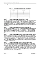
10.3.1.9
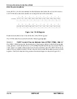
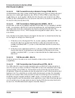
TCCR Transmit Frame Sync Signal Direction (TFSD) - Bit 22
TFSD controls the direction of the FST pin. When TFSD is cleared, FST is an input; when
TFSD is set, FST is an output. See Table 10-2.
10.3.1.10
TCCR Transmit High Frequency Clock Direction (THCKD) - Bit 23
THCKD controls the direction of the HCKT pin. When THCKD is cleared, HCKT is an input;
when THCKD is set, HCKT is an output. See Table 10-2.
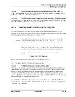
10.3.2
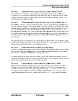
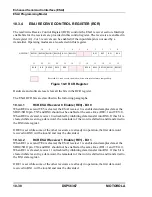
ESAI TRANSMIT CONTROL REGISTER (TCR)
The read/write Transmit Control Register (TCR) controls the ESAI transmitter section.
Interrupt enable bits for the transmitter section are provided in this control register. Operating
modes are also selected in this register. See Figure 10-5.
Hardware and software reset clear all the bits in the TCR register.
The TCR bits are described in the following paragraphs.
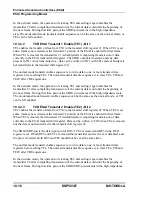
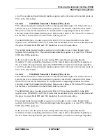
10.3.2.1
TCR ESAI Transmit 0 Enable (TE0) - Bit 0
TE0 enables the transfer of data from TX0 to the transmit shift register #0. When TE0 is set
and a frame sync is detected, the transmit #0 portion of the ESAI is enabled for that frame.
When TE0 is cleared, the transmitter #0 is disabled after completing transmission of data
currently in the ESAI transmit shift register. The SDO0 output is tri-stated, and any data
present in TX0 is not transmitted (i.e., data can be written to TX0 with TE0 cleared; but data is
not transferred to the transmit shift register #0).
The normal mode transmit enable sequence is to write data to one or more transmit data
registers before setting TEx. The normal transmit disable sequence is to clear TEx, TIE and
TEIE after TDE equals one.
11
10
9
8
7
6
5
4
3
2
1
0
X:$FFFFB5
TSWS1 TSWS0 TMOD1 TMOD0 TWA TSHFD
TE5
TE4
TE3
TE2
TE1
TE0
23
22
21
20
19
18
17
16
15
14
13
12
TLIE
TIE
TEDIE
TEIE
TPR
PADC
TFSR
TFSL TSWS4 TSWS3 TSWS2
Reserved bit - read as zero; should be written with zero for future compatibility.
Figure 10-5 TCR Register
Summary of Contents for DSP56367
Page 16: ...xvi MOTOROLA CONTENTS Paragraph Number Title Page Number ...
Page 22: ...xxii MOTOROLA List of Figures Figure Number Title Page Number ...
Page 26: ...xxvi MOTOROLA List of Tables Table Number Title Page Number ...
Page 148: ...4 6 DSP56367 MOTOROLA Design Considerations PLL Performance Issues ...
Page 248: ...9 30 DSP56367 MOTOROLA Serial Host Interface SHI Programming Considerations ...
Page 306: ...10 58 DSP56367 MOTOROLA Enhanced Serial Audio Interface ESAI ESAI Initialization Examples ...
Page 389: ...Bootstrap ROM Contents MOTOROLA DSP56367 A 15 end ...
Page 390: ...A 16 DSP56367 MOTOROLA Bootstrap ROM Contents ...
Page 432: ...C 8 DSP56367 MOTOROLA JTAG BSDL ...
Page 484: ...D 52 DSP56367 MOTOROLA Programmer s Reference ...
Page 490: ...E 6 DSP56367 MOTOROLA Power Consumption Benchmark ...
Page 516: ...F 26 DSP56367 MOTOROLA IBIS Model ...
Page 522: ...Index 6 MOTOROLA Index ...
Page 523: ......


