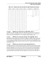
10-26
DSP56367
MOTOROLA
Enhanced Serial Audio Interface (ESAI)
ESAI Programming Model
10.3.3
ESAI RECEIVE CLOCK CONTROL REGISTER (RCCR)
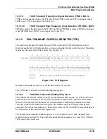
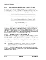
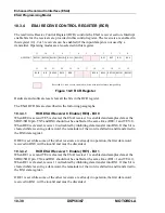
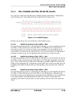
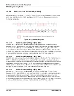
The read/write Receive Clock Control Register (RCCR) controls the ESAI receiver clock
generator bit and frame sync rates, word length, and number of words per frame for the serial
data. The RCCR control bits are described in the following paragraphs (see Figure 10-8).
Hardware and software reset clear all the bits of the RCCR register.
10.3.3.1
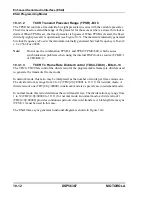
RCCR Receiver Prescale Modulus Select (RPM7–RPM0) - Bits 7–0
The RPM7–RPM0 bits specify the divide ratio of the prescale divider in the ESAI receiver
clock generator. A divide ratio from 1 to 256 (RPM[7:0]=$00 to $FF) may be selected. The bit
clock output is available at the receiver serial bit clock (SCKR) pin of the DSP. The bit clock
output is also available internally for use as the bit clock to shift the receive shift registers. The
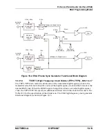
ESAI receive clock generator functional diagram is shown in Figure 10-3.
10.3.3.2
RCCR Receiver Prescaler Range (RPSR) - Bit 8
The RPSR controls a fixed divide-by-eight prescaler in series with the variable prescaler. This
bit is used to extend the range of the prescaler for those cases where a slower bit clock is
desired. When RPSR is set, the fixed prescaler is bypassed. When RPSR is cleared, the fixed
divide-by-eight prescaler is operational (see Figure 10-3). The maximum internally generated
bit clock frequency is Fosc/4, the minimum internally generated bit clock frequency is Fosc/(2
x 8 x 256)=Fosc/4096.
Note:
Do not use the combination RPSR=1 and RPM7-RPM0=$00, which causes
synchronization problems when using the internal DSP clock as source
(RHCKD=1 or RCKD=1).
10.3.3.3
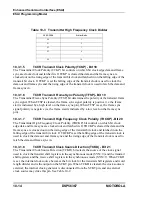
RCCR Rx Frame Rate Divider Control (RDC4–RDC0) - Bits 9–13
The RDC4–RDC0 bits control the divide ratio for the programmable frame rate dividers used
to generate the receiver frame clocks.
11
10
9
8
7
6
5
4
3
2
1
0
X:$FFFFB8
RDC2 RDC1 RDC0 RPSR RPM7 RPM6 RPM5 RPM4 RPM3 RPM2 RPM1 RPM0
23
22
21
20
19
18
17
16
15
14
13
12
RHCK
D
RFSD RCKD RHCKP RFSP
RCKP
RFP3
RFP2
RFP1
RFP0
RDC4 RDC3
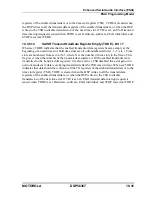
Figure 10-8 RCCR Register
Summary of Contents for DSP56367
Page 16: ...xvi MOTOROLA CONTENTS Paragraph Number Title Page Number ...
Page 22: ...xxii MOTOROLA List of Figures Figure Number Title Page Number ...
Page 26: ...xxvi MOTOROLA List of Tables Table Number Title Page Number ...
Page 148: ...4 6 DSP56367 MOTOROLA Design Considerations PLL Performance Issues ...
Page 248: ...9 30 DSP56367 MOTOROLA Serial Host Interface SHI Programming Considerations ...
Page 306: ...10 58 DSP56367 MOTOROLA Enhanced Serial Audio Interface ESAI ESAI Initialization Examples ...
Page 389: ...Bootstrap ROM Contents MOTOROLA DSP56367 A 15 end ...
Page 390: ...A 16 DSP56367 MOTOROLA Bootstrap ROM Contents ...
Page 432: ...C 8 DSP56367 MOTOROLA JTAG BSDL ...
Page 484: ...D 52 DSP56367 MOTOROLA Programmer s Reference ...
Page 490: ...E 6 DSP56367 MOTOROLA Power Consumption Benchmark ...
Page 516: ...F 26 DSP56367 MOTOROLA IBIS Model ...
Page 522: ...Index 6 MOTOROLA Index ...
Page 523: ......

