10-38
DSP56367
MOTOROLA
Enhanced Serial Audio Interface (ESAI)
ESAI Programming Model
10.3.6
ESAI STATUS REGISTER (SAISR)
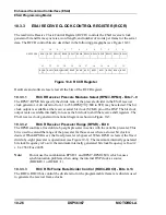
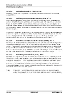
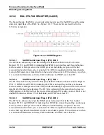
The Status Register (SAISR) is a read-only status register used by the DSP to read the status
and serial input flags of the ESAI. See Figure 10-12. The status bits are described in the
following paragraphs.
10.3.6.1
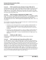
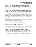
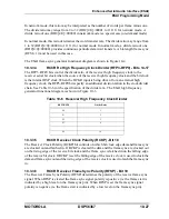
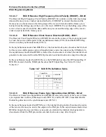
SAISR Serial Input Flag 0 (IF0) - Bit 0
The IF0 bit is enabled only when the SCKR pin is defined as ESAI in the Port Control
Register, SYN=1 and RCKD=0, indicating that SCKR is an input flag and the synchronous
mode is selected. Data present on the SCKR pin is latched during reception of the first
received data bit after frame sync is detected. The IF0 bit is updated with this data when the
receiver shift registers are transferred into the receiver data registers. IF0 reads as a zero when
it is not enabled. Hardware, software, ESAI individual, and STOP reset clear IF0.
10.3.6.2
SAISR Serial Input Flag 1 (IF1) - Bit 1
The IF1 bit is enabled only when the FSR pin is defined as ESAI in the Port Control Register,
SYN =1, RFSD=0 and TEBE=0, indicating that FSR is an input flag and the synchronous
mode is selected. Data present on the FSR pin is latched during reception of the first received
data bit after frame sync is detected. The IF1 bit is updated with this data when the receiver
shift registers are transferred into the receiver data registers. IF1 reads as a zero when it is not
enabled. Hardware, software, ESAI individual, and STOP reset clear IF1.
10.3.6.3
SAISR Serial Input Flag 2 (IF2) - Bit 2
The IF2 bit is enabled only when the HCKR pin is defined as ESAI in the Port Control
Register, SYN=1 and RHCKD=0, indicating that HCKR is an input flag and the synchronous
mode is selected. Data present on the HCKR pin is latched during reception of the first
received data bit after frame sync is detected. The IF2 bit is updated with this data when the
receive shift registers are transferred into the receiver data registers. IF2 reads as a zero when
it is not enabled. Hardware, software, ESAI individual, and STOP reset clear IF2.
11
10
9
8
7
6
5
4
3
2
1
0
X:$FFFFB3
RODF REDF
RDF
ROE
RFS
IF2
IF1
IF0
23
22
21
20
19
18
17
16
15
14
13
12
TODE TEDE
TDE
TUE
TFS
Reserved bit - read as zero; should be written with zero for future compatibility.
Figure 10-12 SAISR Register
Summary of Contents for DSP56367
Page 16: ...xvi MOTOROLA CONTENTS Paragraph Number Title Page Number ...
Page 22: ...xxii MOTOROLA List of Figures Figure Number Title Page Number ...
Page 26: ...xxvi MOTOROLA List of Tables Table Number Title Page Number ...
Page 148: ...4 6 DSP56367 MOTOROLA Design Considerations PLL Performance Issues ...
Page 248: ...9 30 DSP56367 MOTOROLA Serial Host Interface SHI Programming Considerations ...
Page 306: ...10 58 DSP56367 MOTOROLA Enhanced Serial Audio Interface ESAI ESAI Initialization Examples ...
Page 389: ...Bootstrap ROM Contents MOTOROLA DSP56367 A 15 end ...
Page 390: ...A 16 DSP56367 MOTOROLA Bootstrap ROM Contents ...
Page 432: ...C 8 DSP56367 MOTOROLA JTAG BSDL ...
Page 484: ...D 52 DSP56367 MOTOROLA Programmer s Reference ...
Page 490: ...E 6 DSP56367 MOTOROLA Power Consumption Benchmark ...
Page 516: ...F 26 DSP56367 MOTOROLA IBIS Model ...
Page 522: ...Index 6 MOTOROLA Index ...
Page 523: ......

