10-46
DSP56367
MOTOROLA
Enhanced Serial Audio Interface (ESAI)
ESAI Programming Model
When bit number N in TSM is cleared, all the transmit data pins of the enabled transmitters
are tri-stated during transmit time slot number N. The data is still transferred from the transmit
data registers to the transmit shift registers but neither the TDE nor the TUE flags are set. This
means that during a disabled slot, no transmitter empty interrupt is generated. The DSP is
interrupted only for enabled slots. Data that is written to the transmit data registers when
servicing this request is transmitted in the next enabled transmit time slot.
When bit number N in TSM register is set, the transmit sequence is as usual: data is
transferred from the TX registers to the shift registers, transmitted during slot number N, and
the TDE flag is set.
Using the slot mask in TSM does not conflict with using TSR. Even if a slot is enabled in
TSM, the user may chose to write to TSR instead of writing to the transmit data registers TXx.
This causes all the transmit data pins of the enabled transmitters to be tri-stated during the
next slot.
Data written to the TSM affects the next frame transmission. The frame being transmitted is
not affected by this data and would comply to the last TSM setting. Data read from TSM
returns the last written data.
After hardware or software reset, the TSM register is preset to $FFFFFFFF, which means that
all 32 possible slots are enabled for data transmission.
Note:
When operating in normal mode, bit 0 of the mask register must be set, otherwise
no output is generated.
10.3.13
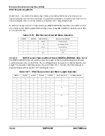
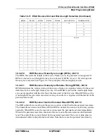
RECEIVE SLOT MASK REGISTERS (RSMA, RSMB)
The Receive Slot Mask Registers (RSMA and RSMB) are two read/write registers used by the
receiver in network mode to determine for each slot whether to receive a data word and
generate a receiver full condition (RDF=1), or to ignore the received data. RSMA and RSMB
should be considered as each containing half of a 32-bit register RSM. See Table 10-17 and
Summary of Contents for DSP56367
Page 16: ...xvi MOTOROLA CONTENTS Paragraph Number Title Page Number ...
Page 22: ...xxii MOTOROLA List of Figures Figure Number Title Page Number ...
Page 26: ...xxvi MOTOROLA List of Tables Table Number Title Page Number ...
Page 148: ...4 6 DSP56367 MOTOROLA Design Considerations PLL Performance Issues ...
Page 248: ...9 30 DSP56367 MOTOROLA Serial Host Interface SHI Programming Considerations ...
Page 306: ...10 58 DSP56367 MOTOROLA Enhanced Serial Audio Interface ESAI ESAI Initialization Examples ...
Page 389: ...Bootstrap ROM Contents MOTOROLA DSP56367 A 15 end ...
Page 390: ...A 16 DSP56367 MOTOROLA Bootstrap ROM Contents ...
Page 432: ...C 8 DSP56367 MOTOROLA JTAG BSDL ...
Page 484: ...D 52 DSP56367 MOTOROLA Programmer s Reference ...
Page 490: ...E 6 DSP56367 MOTOROLA Power Consumption Benchmark ...
Page 516: ...F 26 DSP56367 MOTOROLA IBIS Model ...
Page 522: ...Index 6 MOTOROLA Index ...
Page 523: ......

