Digital Audio Transmitter
DAX Internal Architecture
MOTOROLA
DSP56367
12-9
12.5.7
DAX STATUS REGISTER (XSTR)
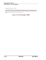
The XSTR is a 24-bit read-only register that contains the DAX status flags. The contents of
the XSTR are shown in Figure 12-2. XSTR is cleared by software reset, hardware reset an by
the stop state. The XSTR bits are described in the following paragraphs.
12.5.7.1
DAX Audio Data Register Empty (XADE)—Bit 0
The XADE status flag indicates that the DAX audio data register XADR and the audio data
buffer XADBUFA are empty (and ready to receive the next frame’s audio data). This bit is set
at the beginning of every frame transmission (more precisely, when channel A audio data is
transferred from XADBUFA to XADSR). When XADE is set and the interrupt is enabled
(XDIE = 1), an audio data register empty interrupt request is sent to the DSP core. XADE is
cleared by writing two channels of audio data to XADR.
12.5.7.2
DAX Transmit Underrun Error Flag (XAUR)—Bit 1
The XAUR status flag is set when the DAX audio data buffers XADBUFA or XADBUFB are
empty and the respective audio data upload occurs. When a DAX underrun error occurs, the
previous frame data will be retransmitted in both channels. When XAUR is set and the
interrupt is enabled (XUIE = 1), an underrun error interrupt request is sent to the DSP core.
This allows programmers to write an exception handling routine for this special case. The
XAUR bit is cleared by reading the XSTR register with XAUR set, followed by writing two
channels of audio data to XADR.
12.5.7.3
DAX Block Transfer Flag (XBLK)—Bit 2
The XBLK flag indicates that the frame being transmitted is the last frame in a block. This bit
is set at the beginning of the transmission of the last frame (the 191st frame). This bit does not
cause any interrupt. However, if XBIE=1 it causes a change in the interrupt vector sent to DSP
core in the event of an audio data register empty interrupt, so that a different interrupt routine
can be called (providing the next non-audio data structures for the next block as well as
storing audio data for the next frame). Writing two channels of audio data to XADR clears this
bit.
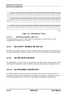
The relative timing of transmit frames and XADE and XBLK flags is shown in Figure 12-3.
Summary of Contents for DSP56367
Page 16: ...xvi MOTOROLA CONTENTS Paragraph Number Title Page Number ...
Page 22: ...xxii MOTOROLA List of Figures Figure Number Title Page Number ...
Page 26: ...xxvi MOTOROLA List of Tables Table Number Title Page Number ...
Page 148: ...4 6 DSP56367 MOTOROLA Design Considerations PLL Performance Issues ...
Page 248: ...9 30 DSP56367 MOTOROLA Serial Host Interface SHI Programming Considerations ...
Page 306: ...10 58 DSP56367 MOTOROLA Enhanced Serial Audio Interface ESAI ESAI Initialization Examples ...
Page 389: ...Bootstrap ROM Contents MOTOROLA DSP56367 A 15 end ...
Page 390: ...A 16 DSP56367 MOTOROLA Bootstrap ROM Contents ...
Page 432: ...C 8 DSP56367 MOTOROLA JTAG BSDL ...
Page 484: ...D 52 DSP56367 MOTOROLA Programmer s Reference ...
Page 490: ...E 6 DSP56367 MOTOROLA Power Consumption Benchmark ...
Page 516: ...F 26 DSP56367 MOTOROLA IBIS Model ...
Page 522: ...Index 6 MOTOROLA Index ...
Page 523: ......


