Timer/ Event Counter
Timer/Event Counter Programming Model
MOTOROLA
DSP56367
13-3
13.3
TIMER/EVENT COUNTER PROGRAMMING MODEL
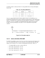
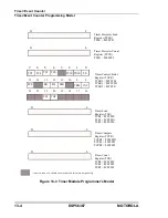
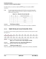
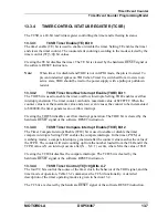
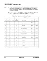
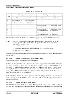
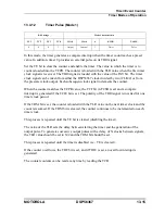
The DSP56367 views each timer as a memory-mapped peripheral with four registers
occupying four 24-bit words in the X data memory space. Either standard polled or interrupt
programming techniques can be used to service the timers. The timer programming model is
shown in Figure 13-3.
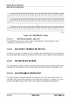
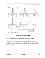
Figure 13-2 Timer Block Diagram
GDB
Control/Status
Register
TCSR
Counter
Timer interrupt/
Timer Control
CLK/2
TIO
Compare
Register
TCPR
=
24
24
DMA request
Logic
Load
Register
Count
Register
TLR
prescaler CLK
TCR
24
24
9
2
24
24
24
24
24
(Timer 0
only)
AA0676
Summary of Contents for DSP56367
Page 16: ...xvi MOTOROLA CONTENTS Paragraph Number Title Page Number ...
Page 22: ...xxii MOTOROLA List of Figures Figure Number Title Page Number ...
Page 26: ...xxvi MOTOROLA List of Tables Table Number Title Page Number ...
Page 148: ...4 6 DSP56367 MOTOROLA Design Considerations PLL Performance Issues ...
Page 248: ...9 30 DSP56367 MOTOROLA Serial Host Interface SHI Programming Considerations ...
Page 306: ...10 58 DSP56367 MOTOROLA Enhanced Serial Audio Interface ESAI ESAI Initialization Examples ...
Page 389: ...Bootstrap ROM Contents MOTOROLA DSP56367 A 15 end ...
Page 390: ...A 16 DSP56367 MOTOROLA Bootstrap ROM Contents ...
Page 432: ...C 8 DSP56367 MOTOROLA JTAG BSDL ...
Page 484: ...D 52 DSP56367 MOTOROLA Programmer s Reference ...
Page 490: ...E 6 DSP56367 MOTOROLA Power Consumption Benchmark ...
Page 516: ...F 26 DSP56367 MOTOROLA IBIS Model ...
Page 522: ...Index 6 MOTOROLA Index ...
Page 523: ......

