Timer/ Event Counter
Timer/Event Counter Programming Model
MOTOROLA
DSP56367
13-7
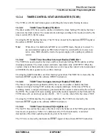
13.3.4
TIMER CONTROL/STATUS REGISTER (TCSR)
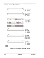
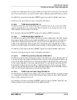
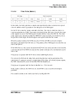
The TCSR is a 24-bit read/write register controlling the timer and reflecting its status.
13.3.4.1
TCSR Timer Enable (TE) Bit 0
The timer enable (TE) bit is used to enable or disable the timer. Setting TE enables the timer
and clears the timer counter. The counter starts counting according to the mode selected by the
timer control (TC[3:0]) bit values.
Clearing the TE bit disables the timer. The TE bit is cleared by the hardware RESET signal or
the software RESET instruction.
Note:
When timer 0 is disabled and TIO0 is not in GPIO mode, the pin is tri-stated. To
prevent undesired spikes on TIO0 when Timer 0 is switched from tri-state to an
active state, TIO0 should be tied to the power supply with a pullup or pulldown
resistor.
13.3.4.2
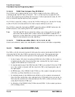
TCSR Timer Overflow Interrupt Enable (TOIE) Bit 1
The TOIE bit is used to enable the timer overflow interrupts. Setting TOIE enables overflow
interrupt generation. The timer counter can hold a maximum value of $FFFFFF. When the
counter value is at the maximum value and a new event causes the counter to be incremented
to $000000, the timer generates an overflow interrupt.
Clearing the TOIE bit disables overflow interrupt generation. The TOIE bit is cleared by the
hardware RESET signal or the software RESET instruction.
13.3.4.3
TCSR Timer Compare Interrupt Enable (TCIE) Bit 2
The Timer Compare Interrupt Enable (TCIE) bit is used to enable or disable the timer
compare interrupts. Setting TCIE enables the compare interrupts. In the timer, PWM, or
watchdog modes, a compare interrupt is generated after the counter value matches the value of
the TCPR. The counter will start counting up from the number loaded from the TLR and if the
TCPR value is N, an interrupt occurs after (N – M + 1) events, where M is the value of TLR.
Clearing the TCIE bit disables the compare interrupts. The TCIE bit is cleared by the
hardware RESET signal or the software RESET instruction.
13.3.4.4
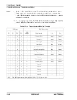
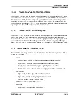
TCSR Timer Control (TC[3:0]) Bits 4–7
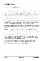
The four TC bits control the source of the timer clock, the behavior of the TIO0 signal, and the
timer mode of operation. Table 13-2 summarizes the TC bit functionality. A detailed
description of the timer operating modes is given in Section 13.4.
The TC bits are cleared by the hardware RESET signal or the software RESET instruction.
Summary of Contents for DSP56367
Page 16: ...xvi MOTOROLA CONTENTS Paragraph Number Title Page Number ...
Page 22: ...xxii MOTOROLA List of Figures Figure Number Title Page Number ...
Page 26: ...xxvi MOTOROLA List of Tables Table Number Title Page Number ...
Page 148: ...4 6 DSP56367 MOTOROLA Design Considerations PLL Performance Issues ...
Page 248: ...9 30 DSP56367 MOTOROLA Serial Host Interface SHI Programming Considerations ...
Page 306: ...10 58 DSP56367 MOTOROLA Enhanced Serial Audio Interface ESAI ESAI Initialization Examples ...
Page 389: ...Bootstrap ROM Contents MOTOROLA DSP56367 A 15 end ...
Page 390: ...A 16 DSP56367 MOTOROLA Bootstrap ROM Contents ...
Page 432: ...C 8 DSP56367 MOTOROLA JTAG BSDL ...
Page 484: ...D 52 DSP56367 MOTOROLA Programmer s Reference ...
Page 490: ...E 6 DSP56367 MOTOROLA Power Consumption Benchmark ...
Page 516: ...F 26 DSP56367 MOTOROLA IBIS Model ...
Page 522: ...Index 6 MOTOROLA Index ...
Page 523: ......

