Timer/ Event Counter
Timer Modes of Operation
MOTOROLA
DSP56367
13-17
13.4.1.4
Timer Event Counter (Mode 3)
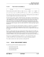
In this mode, the timer counts internal events and issues an interrupt when a preset number of
events is counted. Timer 0 can also count external events.
Set the TE bit to clear the counter and enable the timer. The number of events the timer is to
count is loaded into the TPCR. The counter is loaded with the TLR value when the first timer
clock signal is received. The timer clock signal is provided by the prescaler clock output.
Timer 0 can be also be clocked from the TIO0 input signal. Each subsequent clock signal
increments the counter. If an external clock is used, it must be internally synchronized to the
internal clock and its frequency must be less than the DSP56367 internal operating frequency
divided by 4.
The value of the INV bit in the TCSR determines whether low-to-high (0 to 1) transitions or
high-to-low (1 to 0) transitions increment the counter. If the INV bit is set, high-to-low
transitions increment the counter. If the INV bit is cleared, low-to-high transitions increment
the counter.
When the counter matches the value contained in the TCPR, the TCF bit in the TCSR is set
and a compare interrupt is generated if the TCIE bit is set. If the TRM bit is set, the counter is
loaded with the value of the TLR when the next timer clock is received, and the count is
resumed. If TRM bit is cleared, the counter continues to be incremented on each timer clock.
This process is repeated until the timer is disabled (i.e., TE is cleared). If the counter
overflows, the TOF bit is set, and if TOIE is set, an overflow interrupt is generated.
The counter contents can be read at any time by reading the TCR.
13.4.2
SIGNAL MEASUREMENT MODES
The following signal measurement modes are provided:
•
Measurement input width
•
Measurement input period
•
Measurement capture
Bit Settings
Mode Characteristics
TC3
TC2
TC1
TC0
TIO0
Clock
#
KIND
NAME
0
0
1
1
Input
External
3
Timer
Event Counter
Summary of Contents for DSP56367
Page 16: ...xvi MOTOROLA CONTENTS Paragraph Number Title Page Number ...
Page 22: ...xxii MOTOROLA List of Figures Figure Number Title Page Number ...
Page 26: ...xxvi MOTOROLA List of Tables Table Number Title Page Number ...
Page 148: ...4 6 DSP56367 MOTOROLA Design Considerations PLL Performance Issues ...
Page 248: ...9 30 DSP56367 MOTOROLA Serial Host Interface SHI Programming Considerations ...
Page 306: ...10 58 DSP56367 MOTOROLA Enhanced Serial Audio Interface ESAI ESAI Initialization Examples ...
Page 389: ...Bootstrap ROM Contents MOTOROLA DSP56367 A 15 end ...
Page 390: ...A 16 DSP56367 MOTOROLA Bootstrap ROM Contents ...
Page 432: ...C 8 DSP56367 MOTOROLA JTAG BSDL ...
Page 484: ...D 52 DSP56367 MOTOROLA Programmer s Reference ...
Page 490: ...E 6 DSP56367 MOTOROLA Power Consumption Benchmark ...
Page 516: ...F 26 DSP56367 MOTOROLA IBIS Model ...
Page 522: ...Index 6 MOTOROLA Index ...
Page 523: ......

