7 - 26
DSP96002 USER’S MANUAL
MOTOROLA
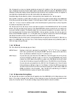
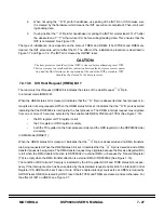
In DMA Mode (DMAE=1), TREQ must be set or cleared by software to select the direction of DMA transfers.
Setting TREQ defines the direction of DMA transfer to be from external DMA
→
96002, and enables the
—
H
–
R pin to request these data transfers.
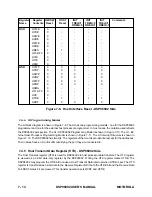
See Figure 7-15 and Figure 7-16 for a summary of the effect of TREQ on the
—
H
–
R pin. TREQ is cleared
by HW/SW reset.
7.4.13.6
ICS Transmitter Ready Request Enable (TYEQ) Bit 5
TYEQ is used to enable interrupts via the Host Request
—
H
–
R pin when the Transmitter Ready (TRDY)
status bit is set. When TYEQ is cleared, TRDY interrupts are disabled. When TYEQ is set, the Host Request
—
H
–
R pin will be asserted if TRDY is set.
See Figure 7-15 for a summary of the effect of TYEQ on the
—
H
–
R pin. TYEQ is cleared by HW/SW reset.
In DMA Mode (DMAE=1), TYEQ must be cleared.
7.4.13.7
ICS Initialize (INIT) Bit 6
The INIT bit is used by the host processor to force initialization of the HI hardware. This may or may not be
necessary, depending on the software design of the interface.
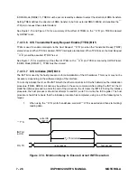
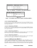
To correctly initialize the HI, set the INIT bit with the other control bits in ICS which determine the initialization
procedure (TREQ, RREQ). All bits may be written in the same command. After setting the INIT bit, the HI
starts the initialize procedure, and at the end of the procedure, the HI clears the INIT bit. During the initialize
procedure, the host processor should not attempt to read RX, write TX or write the ICS register. The host
processor should first ensure that the Initialize procedure has completed, using one of the following tech-
niques:
1.
When using the
—
H
–
R pin for handshake, wait until
—
H
–
R is asserted and then start writing/
reading data.
—
T
–
S
INIT bit
in ICS
RX, TX
no accesses
first access
3T
c
+Th minimum
write ICS
INIT=1
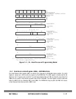
Figure 7-14. Minimum Delay to Ensure Correct INIT Execution
Summary of Contents for DSP96002
Page 3: ...1 2 DSP96002 USER S MANUAL MOTOROLA ...
Page 38: ...MOTOROLA DSP96002 USER S MANUAL 3 15 Figure 3 4 Modulo Arithmetic Unit Block Diagram ...
Page 39: ...3 16 DSP96002 USER S MANUAL MOTOROLA ...
Page 53: ...4 14 DSP96002 USER S MANUAL MOTOROLA ...
Page 76: ...MOTOROLA DSP96002 USER S MANUAL 5 23 Figure 5 8 Address Modifier Summary ...
Page 86: ...6 10 DSP96002 USER S MANUAL MOTOROLA ...
Page 101: ...MOTOROLA DSP96002 USER S MANUAL 7 15 Figure 7 9 HI Block Diagram One Port ...
Page 140: ...7 54 DSP96002 USER S MANUAL MOTOROLA ...
Page 166: ...9 10 DSP96002 USER S MANUAL MOTOROLA ...
Page 181: ...MOTOROLA DSP96002 USER S MANUAL 10 15 Figure 10 8 Program Address Bus FIFO ...
Page 337: ...MOTOROLA DSP96002 USER S MANUAL A 149 ...
Page 404: ...A 216 DSP96002 USER S MANUAL MOTOROLA PC xxxx D ...
Page 460: ...A 272 DSP96002 USER S MANUAL MOTOROLA SIOP Not affected ...
Page 484: ...A 296 DSP96002 USER S MANUAL MOTOROLA SSH PC SSL SR SP 1 SP ...
Page 519: ...MOTOROLA DSP96002 USER S MANUAL A 331 ...
Page 718: ...MOTOROLA DSP96002 USER S MANUAL B 199 ...
Page 871: ... MOTOROLA INC 1994 MOTOROLA TECHNICAL DATA SEMICONDUCTOR M Addendum ...
Page 888: ...MOTOROLA INDEX 1 INDEX ...
Page 889: ......

