MOTOROLA
DSP96002 USER’S MANUAL
8 - 11
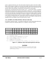
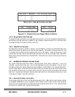
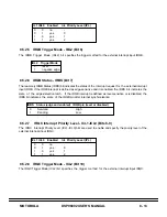
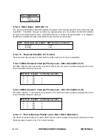
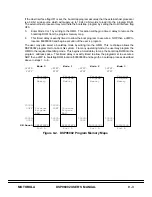
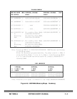
IxL2 Trigger Mode IRxS Status
0 level 0 Serviced
1 neg. edge 1 Pending
xxL1 xxL0 Enabled Int. Priority Level (IPL)
0 0 no -
0 1 yes 0
1 0 yes 1
1 1 yes 2
Figure 8-11. External Interrupt Trigger Mode and Status
Figure 8-10. Interrupt Priority Level Bits
8.4.5 Illegal Instruction Interrupt
The illegal instruction interrupt is a non-maskable interrupt which is serviced immediately following the ille-
gal instruction interrupt instruction (ILLEGAL) or upon loading an illegal instruction in the instruction latch.
The illegal instruction interrupt is a priority 3 interrupt.
8.4.6 Stack Error Interrupt
The Stack Error interrupt is a priority 3 interrupt. It is generated by turning on the Stack Error flag in the
Stack Pointer register, generally due to improper stack operation. The Stack Error flag will remain set until
it is cleared by some instruction that explicitly writes into the SP register. Since the IPL level (3) of this
interrupt does not mask other pending interrupts of this same level, it is recommended that the Stack Error
flag be cleared by the first instruction of the Stack Error interrupt service routine in order not to get the same
request again.
8.5
INTERRUPT PRIORITY STRUCTURE
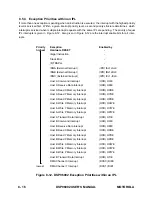
Four levels of interrupt priority are provided. Interrupt priority levels (IPLs) numbered 0, 1, and 2, are
maskable. Level 0 is the lowest level. Level 3 is the highest level, and is nonmaskable. The only level 3
interrupts are Stack Error, Reset, Illegal Instruction (ILLEGAL) and (F)TRAPcc. The interrupt mask bits (I1,
I0) in the status register reflect the current processor priority level and indicate the interrupt minimum priority
level needed for an interrupt source to interrupt the processor. Figure 8-8 gives a description of the interrupt
mask bits. Interrupts are inhibited for all priority levels less than the current processor priority level. Level
3 interrupts can always interrupt the processor.
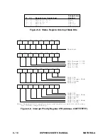
8.5.1 Interrupt Priority Levels (IPL)
The interrupt priority level for each on-chip peripheral device (Host, DMA) and for each external interrupt
source (IRQA, IRQB, IRQC) can be programmed under software control. Each on-chip or external periph-
eral device can be programmed to one of the three maskable priority levels (IPL 0, 1, or 2). Interrupt priority
levels are set by writing to the Interrupt Priority Register.
Summary of Contents for DSP96002
Page 3: ...1 2 DSP96002 USER S MANUAL MOTOROLA ...
Page 38: ...MOTOROLA DSP96002 USER S MANUAL 3 15 Figure 3 4 Modulo Arithmetic Unit Block Diagram ...
Page 39: ...3 16 DSP96002 USER S MANUAL MOTOROLA ...
Page 53: ...4 14 DSP96002 USER S MANUAL MOTOROLA ...
Page 76: ...MOTOROLA DSP96002 USER S MANUAL 5 23 Figure 5 8 Address Modifier Summary ...
Page 86: ...6 10 DSP96002 USER S MANUAL MOTOROLA ...
Page 101: ...MOTOROLA DSP96002 USER S MANUAL 7 15 Figure 7 9 HI Block Diagram One Port ...
Page 140: ...7 54 DSP96002 USER S MANUAL MOTOROLA ...
Page 166: ...9 10 DSP96002 USER S MANUAL MOTOROLA ...
Page 181: ...MOTOROLA DSP96002 USER S MANUAL 10 15 Figure 10 8 Program Address Bus FIFO ...
Page 337: ...MOTOROLA DSP96002 USER S MANUAL A 149 ...
Page 404: ...A 216 DSP96002 USER S MANUAL MOTOROLA PC xxxx D ...
Page 460: ...A 272 DSP96002 USER S MANUAL MOTOROLA SIOP Not affected ...
Page 484: ...A 296 DSP96002 USER S MANUAL MOTOROLA SSH PC SSL SR SP 1 SP ...
Page 519: ...MOTOROLA DSP96002 USER S MANUAL A 331 ...
Page 718: ...MOTOROLA DSP96002 USER S MANUAL B 199 ...
Page 871: ... MOTOROLA INC 1994 MOTOROLA TECHNICAL DATA SEMICONDUCTOR M Addendum ...
Page 888: ...MOTOROLA INDEX 1 INDEX ...
Page 889: ......


