C-22
DSP96002 USER’S MANUAL
MOTOROLA
C.1.5.2
Multiply unit
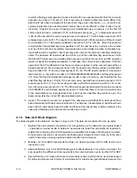
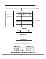
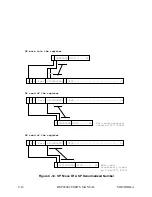
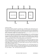
The multiply unit consists of a hardware multiplier, an exponent adder, and a control unit, as shown in Figure
C-17. The multiply unit accepts two 44 bit input operands for floating point multiplications, each consisting
of a sign bit, eleven exponent bits, the explicit integer bit, and 31 fractional bits. Note that for full double pre-
cision operands, as obtained by double precision MOVEs, the least significant 8 bits of the fraction are sim-
ply truncated. Multiply operations occur in parallel with and independent of data moves over the X and Y
data buses.
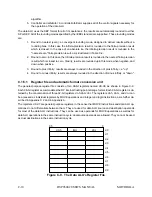
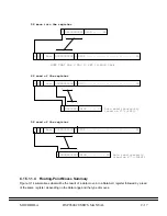
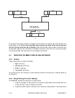
The hardware multiplier accepts the two 32-bit mantissas (integer bit + 31 bit fraction), and delivers a 64 bit
result, as shown in Figure C-18. This result is automatically rounded to a 32-bit mantissa for SEP arithmetic
or a 24 bit mantissa for SP arithmetic, as specified by the instruction opcode. The result is stored into the
mantissa portion of the destination register.
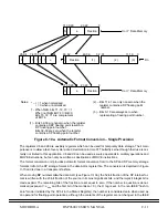
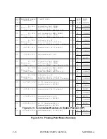
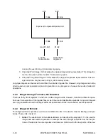
The exponent adder takes the two unsigned (i. e., biased) operand exponents, adds them together, and
subtracts one bias, resulting in an 11-bit biased exponent which is stored in the exponent part of the floating
point format in the destination register, as depicted in Figure C-19.
C.1.5.3
Adder/Subtracter Unit
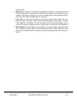
The adder/subtracter is depicted in Figure C-20, and consists of a barrel shifter and normalization unit, an
add unit, a subtract unit, an exponent comparator and update unit and a special function unit. The adder/
subtracter unit accepts 44-bit floating point operands, and delivers 44-bit results. The adder/subtracter op-
erations deliver the sum and the difference of the same two floating point operands in a single instruction
cycle. In addition, the barrel shifter used for mantissa alignment in floating point additions and subtractions
is used for executing multibit shifts for fixed point operation. The adder/subtracter operates in parallel with
and independent of data moves over the X and Y data buses.
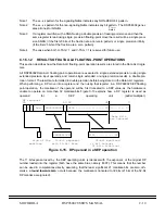
The add unit is a high speed 32-bit adder, used in all floating-point non-multiply operations. For floating point
operations, 32-bit mantissas (1 integer bit and 31 fractional bits) are first "aligned" for floating point addition
in the barrel shifter and normalization unit, after which they are added in the add unit. The result is then
rounded to 32 bits for SEP results, and to 24 bits for SP results, as indicated by the instruction opcode. The
type of rounding implemented depends on the rounding mode bits in the MR register. The rounded result is
stored in the middle portion (mantissa) of the destination register. This is illustrated in Figure C-21
The subtract unit is a high speed 32-bit adder/subtracter, used in all floating-point non-multiply operations
and in all fixed point operations delivering a 32-bit result. For floating point operations, 32-bit mantissas (1
integer bit and 31 fractional bits) are first "aligned" for floating point subtraction in the barrel shifter and nor-
malization unit, after which they are subtracted in the subtract unit. The result is then rounded to 32 bits for
SEP results, and to 24 bits for SP results, as indicated by the instruction opcode. The type of rounding im-
plemented depends on the rounding mode bits in the MR register. The rounded result is stored in the middle
portion (mantissa) of the destination register for floating point operations, and in the low portion for fixed-
point operations. This is illustrated in Figure C-21.
The barrel shifter/normalization unit is used for the alignment of the two operand mantissas, needed for ad-
dition/subtraction of two floating point numbers. The barrel shifter is a 32-bit left-right multibit shifter, which
is also used in fixed point arithmetic and logic shifting operations with a 32-bit result. For the addition of two
floating point operands, the barrel shifter receives the exponent difference of the two operand exponents
from the exponent comparator and update unit, and uses this difference to align the mantissas for addition.
For example, if the biased exponent of the first floating point operand equals 10 and the biased exponent
of the second floating point operand equals 13, the mantissa of the first operand will be right shifted by three
Summary of Contents for DSP96002
Page 3: ...1 2 DSP96002 USER S MANUAL MOTOROLA ...
Page 38: ...MOTOROLA DSP96002 USER S MANUAL 3 15 Figure 3 4 Modulo Arithmetic Unit Block Diagram ...
Page 39: ...3 16 DSP96002 USER S MANUAL MOTOROLA ...
Page 53: ...4 14 DSP96002 USER S MANUAL MOTOROLA ...
Page 76: ...MOTOROLA DSP96002 USER S MANUAL 5 23 Figure 5 8 Address Modifier Summary ...
Page 86: ...6 10 DSP96002 USER S MANUAL MOTOROLA ...
Page 101: ...MOTOROLA DSP96002 USER S MANUAL 7 15 Figure 7 9 HI Block Diagram One Port ...
Page 140: ...7 54 DSP96002 USER S MANUAL MOTOROLA ...
Page 166: ...9 10 DSP96002 USER S MANUAL MOTOROLA ...
Page 181: ...MOTOROLA DSP96002 USER S MANUAL 10 15 Figure 10 8 Program Address Bus FIFO ...
Page 337: ...MOTOROLA DSP96002 USER S MANUAL A 149 ...
Page 404: ...A 216 DSP96002 USER S MANUAL MOTOROLA PC xxxx D ...
Page 460: ...A 272 DSP96002 USER S MANUAL MOTOROLA SIOP Not affected ...
Page 484: ...A 296 DSP96002 USER S MANUAL MOTOROLA SSH PC SSL SR SP 1 SP ...
Page 519: ...MOTOROLA DSP96002 USER S MANUAL A 331 ...
Page 718: ...MOTOROLA DSP96002 USER S MANUAL B 199 ...
Page 871: ... MOTOROLA INC 1994 MOTOROLA TECHNICAL DATA SEMICONDUCTOR M Addendum ...
Page 888: ...MOTOROLA INDEX 1 INDEX ...
Page 889: ......

